Tool/software:
Dear support team,
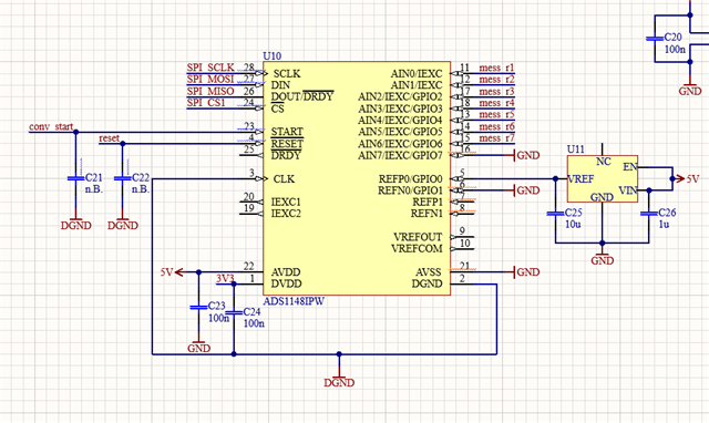
I am currently developing a test system where I am using 4 ADC´s to convert the measured voltage of shunt resistors. The ADS1148 is communicating with a Raspberry Pi via SPI. I use 4.096V as Vref.
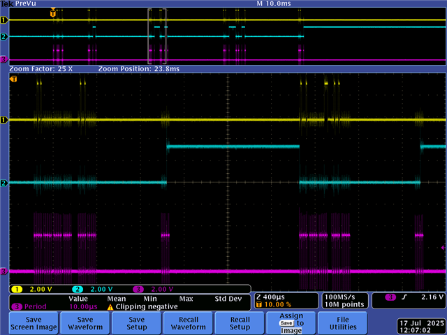
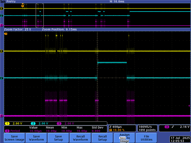
My 1.problem: I think my SPI communication is right and I already measured the communication (picture appended) but no matter which voltage I put on an input pin, the Raspberry Pi reads = or 0.0005V (something like this).
I also read read the dos and donts in the data sheets and saw that maybe my supply is wrong for measuring with Ground but I also tested to measure AIN0 and AIN6 where AIN0 is at 2V and AIN6 is at 200 mV. So the Supply of GND and 5V shouldn´t be a problem.
I will also attache my Code which i am using for testing the ADC. (Sorry for the confusing structure, I changed a lot during testing  )
)
ps: If you find something else that is wrong, feel free to tell me.
Thank you for your help and kind Regards!
#include <stdio.h>
#include <stdlib.h>
#include <stdarg.h>
#include <stdint.h>
#include <unistd.h>
#include <string.h>
#include <sys/timex.h>
#include <sys/stat.h>
#include <sys/resource.h>

#include <fcntl.h>
#include <sys/ioctl.h>
#include <linux/spi/spidev.h>
#include <linux/i2c-dev.h>
#include <sys/resource.h>

#include <pigpio.h>
#include <stdbool.h>

/*
gcc -o ADC_Test_3 ADC_Test_3.c -lpigpio -lrt -lpthread

sudo ./ADC_Test_3

*/
/*
20240502: f_write_result_file:  l_char[55] --> l_char[65]
*/
// +++++++++++++++++++++++++++++++++++++++++++++++++++++++++++
#define  cGlitchFilter  30000 // glitch filter time in us

#define cfg_I2t_threshold  "I2t_threshold"   //threshold for I2t value to trigger
#define cfg_timeout        "timeout"         // timeout in [s] to build I2t value
#define cfg_I_threshold    "I_threshold"     //threshold for I value to trigger measuring
#define cfg_t_turnoff      "t_turnoff"       //threshold for I value to trigger measuring

#define PFAD1		12
#define PFAD2		13
#define PFAD3		14
#define PFAD4		15
#define PFAD5		16
#define PFAD6		18
#define PFAD7		19
#define PFAD8		20
#define PFAD9		21
#define PFAD10		23
#define PFAD11		24
#define PFAD12		25

#define reset	6
#define conv_start	5
#define DL_Trigger	26

//SPI
#define CS1			4
#define CS2			17
#define CS3			27
#define CS4			22
/*
#define SPI_CLK        23     //SPI SPI_CLK
#define MISO1          19    //SPI MISO
#define MOSI           21   //SPI MOSI
//#define SPI_CS         25    //SPI SPI_CS
*/

//I2C
#define I2C_BUS 		"/dev/i2c-1"
#define MCP23017_ADDR 	0x20


#define cFilenameSize   37
#define cDateTimeSize   19


// ----------

// ----------

static const char *device = "/dev/spidev0.0" ;
static uint32_t    speed  = 100000 ;				// 4000000 is ok
static uint8_t     mode   = SPI_MODE_1 ;			// spi mode
static uint8_t     bits   = 8 ;						//
const int cs_gpio[4] = {4, 17, 27, 22}; 		//GPIO´s für CS
// -----------------------------------------------------------


typedef struct {
   char value;             // value  0,1
   char value_changed;     // value has changed
   unsigned T_deglitch;    //T_deglitch
   unsigned tick_1;
   unsigned cc;            //count where we are in time for deglitch
} timed_pin_t;

timed_pin_t  g_IN1;			// IN1 turns off program
timed_pin_t  g_IN2;			// enable current measument
timed_pin_t  g_Enable;		// operation is activated
timed_pin_t  g_LED_I;		// RPI status LED3
timed_pin_t  g_Trenner;		// pyro main switch
// -----------------------------------------------------------
enum status {
   cStatusWaitForEnable,               // status: wait for gENABLE PIN == 1
   cStatusWaitForOperation,            // status: wait for gENABLE PIN == 1 && IN2 == 1
   cStatusWaitForCurrent,              // status: wait for high current
   cStatusI2t,                         // status: current flowing, build I2t integral
   cStatusIturnoff,                    // status: turning off I, takes time
   cStatusI2tDone,                     // status: built I2t integral, fuse bit is set
   cStatusEnd,                         // status: program is stopped
   cStatusError                        // status: error, problem
};
char status_name[8][30] = {
   "cStatusWaitForEnable",
   "cStatusWaitForOperation",
   "cStatusWaitForCurrent",
   "cStatusI2t",
   "cStatusIturnoff",
   "cStatusI2tDone",
   "cStatusEnd",
   "cStatusError"
};

enum status    g_status,			// actual status
               g_status_1;			// status before


unsigned    g_tick, g_tick_1
            //,g_rising_edge_enable             // rising edge of GENABLE
            ;
int         bb									// decision variable
            ,g_fdevice							// serial device
            ;
int g_secs, g_mics;						// time variables

float	    g_I2t_threshold, 			// config: I2t threshold
            g_timeout, 					// config: timeout
            g_I_threshold,				// config: I threshold
            g_i2t;						// measured, calculated I2t            ;
unsigned    g_t_i,					// time elapsed since current has been detected
            g_int_timeout,			// integer value of timeout in [us] of config file
            g_t_turnoff,            // time in [us] read from config file
            g_t_turnoff_t,          // time in [us] acutual time plus g_t_turnoff
			g_t_turnoff_t_index		// when was I turned off
            ;

FILE        *p_result_file, *p_log_file; // result and log file pointer
                                 // ./logs/YYMMDD_hh-mm-ss_I2t_res.txt
char        g_result_file[cFilenameSize] = "./logs/";
                                 // ./logs/YYMMDD_hh-mm-ss_I2t_log.txt
char        g_log_file[cFilenameSize] = "./logs/";
char        g_date_time[cDateTimeSize]       // general use
            ,g_date_time_I[cDateTimeSize]    // time stamp of first time I > I threshold
            ,g_char1[50]= "";				 // general use
            ;
time_t      g_rawtime_1st_I,                 // time stamp of first time I > I threshold
            g_rawtime_turnoff                // time stamp when I is turned off
            ;
struct  tm  *g_info;                         // for time string

struct I_of_t_t
{
   float i;                      // value
   float i2;                     //i² of this t
   unsigned t;                   //delta t to last time t
   uint8_t turnoff;              // is current turned off
   struct I_of_t_t *p_prev;      // p to previous element
   struct I_of_t_t *p_next;      // p to next element
};
struct I_of_t_t *g_i;           // actual element
struct I_of_t_t *g_i1st;        // 1st element
struct I_of_t_t *g_ilast;       // last element

// ----------
int g_cc = 0;					// count steps while measuruing current
int g_ret = 0;					// g return variable
uint16_t g_value = 0      ;		// ADC value
uint32_t g_tick_0, g_tick_1;	// acutual tick, tick before
float g_x =1.1;					// float variable for ADC
double adc_values[4][7];		// Matrix for values

unsigned char g_tx[]   = { 0x01, 0x80, 0x00 } ;		// tx array
unsigned char g_rx[]   = { 0x00, 0x00, 0x00 } ;		// rx array
struct spi_ioc_transfer g_spi[1];					// SPI array
// ----------
typedef struct{
	int value;
	int sum;
	bool disabled;
	unsigned tick_1;
	unsigned time;
	time_t t_off;
} Pfad;

int adc_gpios[4][7] =
{
	{12, 13, 14, 15, 16, 18, 19},     //ADC 0
	{20, 21, 23, 24, 25, 7, 0},       //ADC 1, ab ch5 Adresse für GPIO-Expander
	{7, 0, 6, 1, 5, 2, 4},            //ADC 2, Adresse für GPIO-Expander
	{3, 3, 4, 2, 5, 1, 6}             //ADC 3, Adresse für GPIO-Expander
};
Pfad pfade [4][7]; //Matrix alle Pfade
Pfad *p; //Hilfsvariable auf aktuellen Pfad
bool control; //Hilfsvariable Pfad Okay/Nicht okay?
int pin; //Variable für Pin bei Enable/disable Pfad
double Vref = 4.096;
double gain = 1.0;
double shunt = 0.1;

// ---------------  SPI
// ******************************************************************
// -----------------------------------------------------------
void  f_INIT() {

//GPIO Outputs setzen mit pigpio-Bibliothek
gpioSetMode(PFAD1	, PI_OUTPUT);
gpioSetMode(PFAD2	, PI_OUTPUT);
gpioSetMode(PFAD3	, PI_OUTPUT);
gpioSetMode(PFAD4	, PI_OUTPUT);
gpioSetMode(PFAD5	, PI_OUTPUT);
gpioSetMode(PFAD6	, PI_OUTPUT);
gpioSetMode(PFAD7	, PI_OUTPUT);
gpioSetMode(PFAD8	, PI_OUTPUT);
gpioSetMode(PFAD9	, PI_OUTPUT);
gpioSetMode(PFAD10	, PI_OUTPUT);
gpioSetMode(PFAD11	, PI_OUTPUT);
gpioSetMode(DL_Trigger	, PI_OUTPUT);
gpioSetMode(reset	, PI_OUTPUT);
gpioSetMode(conv_start	, PI_OUTPUT);
//SPI und I2C als Outputs setzen?
gpioSetMode(CS1, PI_OUTPUT);
gpioSetMode(CS2, PI_OUTPUT);
gpioSetMode(CS3, PI_OUTPUT);
gpioSetMode(CS4, PI_OUTPUT);
gpioSetMode(PFAD1, PI_OUTPUT);
gpioSetMode(PFAD9, PI_OUTPUT);
gpioWrite(reset, 1);
}

// -----------------------------------------------------------

int  f_INIT_SPI() {

int l_ret   =0;

memset( &g_spi, 0, sizeof(g_spi) ) ;

g_spi[0].tx_buf        = (unsigned long)g_tx ;
g_spi[0].rx_buf        = (unsigned long)g_rx ;
//g_spi[0].len           = 3 ;
g_spi[0].delay_usecs   = 0 ;
g_spi[0].speed_hz      = speed ;
g_spi[0].bits_per_word = bits ;
g_spi[0].cs_change     = 0 ;

   g_fdevice = open( device, O_RDWR ) ;
   if( g_fdevice < 0 )
   {
      fprintf( stderr, "can't open device\n" ) ;
      return 1 ;
   }

   l_ret = ioctl( g_fdevice, SPI_IOC_WR_MODE, &mode ) ;
   if( l_ret == -1 )
   {
      close( g_fdevice ) ;
      fprintf( stderr, "can't set mode\n" ) ;
      return 2 ;
   }

   l_ret = ioctl( g_fdevice, SPI_IOC_WR_BITS_PER_WORD, &bits ) ;
   if( l_ret == -1 )
   {
      close( g_fdevice ) ;
      fprintf( stderr, "can't set bits\n" ) ;
      return 3 ;
   }

   l_ret = ioctl( g_fdevice, SPI_IOC_WR_MAX_SPEED_HZ, &speed ) ;
   if( l_ret == -1 )
   {
      close( g_fdevice ) ;
      fprintf( stderr, "can't set speed\n" ) ;
      return 4 ;
   }
	return 0;
}
// -----------------------------------------------------------
int f_READ_SPI() {
// read value of ADC
	g_tick_1 = g_tick_0;
	g_tick_0 = gpioTick();

	g_spi[0].len = 4;
    g_spi[0].tx_buf = (unsigned long)g_tx;
    g_spi[0].rx_buf = (unsigned long)g_rx;

    g_tx[0] = 0x12; // RDATA command
    g_tx[1] = 0x00; // 3 leere Bytes zum Lesen des Werts
    g_tx[2] = 0x00;
    g_tx[3] = 0x00;
g_ret = ioctl( g_fdevice, SPI_IOC_MESSAGE(1), &g_spi ) ;
if( g_ret == -1 )
   {
   //close( g_fdevice ) ;
   fprintf( stderr, "can't transfer data\n" ) ;
   //return 5 ;
   }
else {
   g_value = (int) (( (g_rx[1] & 0x0F) << 16) | (g_rx[2] << 8) | g_rx[3]  );
   //printf( "%.3f .. %d\n", g_x, g_tick_0 - g_tick_1 );
   return g_value;
   }

}
// -----------------------------------------------------------
void f_select_adc(int adc) {
    for (int i = 0; i < 4; i++) {
        //gpioWrite(cs_gpio[i], (i == adc) ? 0 : 1); //nur CS von ausgewähltem ADC wird auf 0 (aktiv) gesetzt
        gpioWrite(cs_gpio[0], 1);
        gpioWrite(cs_gpio[1], 1);
        gpioWrite(cs_gpio[2], 1);
        gpioWrite(cs_gpio[3], 1);
        gpioWrite(cs_gpio[adc], 0);
    }
}
// -----------------------------------------------------------

void f_select_channel(int adc, int channel)
{

	    f_select_adc(adc);
    usleep(10000);

    // 1. MUX0 schreiben (WREG)
    g_tx[0] = 0x42; // WREG, ab Adresse 0x00
    g_tx[1] = 0x00; // 1 Register = 0x00
    g_tx[2] = (channel << 4) | 0x07; // AIN[channel] gegen AIN7

    g_spi[0].len = 3;
    g_spi[0].tx_buf = (unsigned long)g_tx;
    g_spi[0].rx_buf = (unsigned long)g_rx;

    if (ioctl(g_fdevice, SPI_IOC_MESSAGE(1), &g_spi[0]) < 1) {
        perror("SPI write error");
        return;
    }


    usleep(2000);

    // 2. RREG Befehl senden
    g_tx[0] = 0x22; // RREG ab Adresse 0x00
    g_tx[1] = 0x00; // 1 Register = 0x00
    g_tx[2] = 0x00;

    g_spi[0].len = 2;
    g_spi[0].tx_buf = (unsigned long)g_tx;
    g_spi[0].rx_buf = (unsigned long)g_rx;

    if (ioctl(g_fdevice, SPI_IOC_MESSAGE(1), &g_spi[0]) < 1) {
        perror("SPI read command error");
        return;
    }

    // 3. 1 Byte Dummy senden, um Register zu lesen
    uint8_t dummy_tx = 0x00;
    uint8_t mux_value = 0;

    g_spi[0].len = 1;
    g_spi[0].tx_buf = (unsigned long)&dummy_tx;
    g_spi[0].rx_buf = (unsigned long)&mux_value;

    if (ioctl(g_fdevice, SPI_IOC_MESSAGE(1), &g_spi[0]) < 1) {
        perror("SPI read register value error");
        return;
    }

    printf("MUX0-Register gesetzt: 0x%02X (AIN%d vs AIN7) ADC: %d\n", mux_value, channel, adc);


		/*f_select_adc(adc);
	usleep(100);
	//Kanal auswählen
	g_tx[0] = 0x42; // WREG, Start bei 0x00
	g_tx[1] = 0x01; // nur ein Register (MUX0)
	g_tx[2] = (channel << 4 ) | 0x07 ; // channel gegen Kanal 7
	if(ioctl( g_fdevice, SPI_IOC_MESSAGE(1), &g_spi ) < 1){
		perror("SPI write error");
	}
	usleep(200);
	g_tx[0] = 0x22; // RREG, Start bei 0x00
	g_tx[1] = 0x01; // nur ein Register (MUX0)
	g_tx[2] = 0x00; // channel gegen Kanal 7
	if(ioctl( g_fdevice, SPI_IOC_MESSAGE(1), &g_spi ) < 1){
		perror("SPI write error");
	}

	printf("aktueller KanaL: %d, %d, %d\n", g_rx[0], g_rx[1], g_rx[2]);*/
}
// -----------------------------------------------------------
void f_read_adc_channel(int adc, int channel)
{
	//f_select_adc(adc);
	//usleep(12000);
	g_spi[0].len = 2;
    g_spi[0].tx_buf = (unsigned long)g_tx;
    g_spi[0].rx_buf = (unsigned long)g_rx;
	//START command
	g_tx[0] = 0x08;
    g_tx[1] = 0x00;
    g_tx[2] = 0x00;
	if(ioctl( g_fdevice, SPI_IOC_MESSAGE(1), &g_spi ) < 1){
		perror("SPI write error");
	}
	usleep(12000);
	int value = f_READ_SPI();

		double voltage = (value) * (Vref / (gain * 8388608.0));//Umrechnung
		double current = voltage / shunt;
		printf("aktueller Wert: %f\n", voltage);
		adc_values[adc][channel] = voltage; //In Matrix speichern

	//FÜr Test:
	// 2. RREG Befehl senden
    g_tx[0] = 0x22; // RREG ab Adresse 0x00
    g_tx[1] = 0x00; // 1 Register = 0x00
    g_tx[2] = 0x00;

    g_spi[0].len = 2;
    g_spi[0].tx_buf = (unsigned long)g_tx;
    g_spi[0].rx_buf = (unsigned long)g_rx;

    if (ioctl(g_fdevice, SPI_IOC_MESSAGE(1), &g_spi[0]) < 1) {
        perror("SPI read command error");
        return;
    }
    usleep(500);

    // 3. 1 Byte Dummy senden, um Register zu lesen
    uint8_t dummy_tx = 0x00;
    uint8_t mux_value = 0;

    g_spi[0].len = 1;
    g_spi[0].tx_buf = (unsigned long)&dummy_tx;
    g_spi[0].rx_buf = (unsigned long)&mux_value;

    if (ioctl(g_fdevice, SPI_IOC_MESSAGE(1), &g_spi[0]) < 1) {
        perror("SPI read register value error");
        return;
    }


		printf("MUX0-Register gelesen: 0x%02X (AIN%d vs AIN6) ADC: %d\n", mux_value, channel, adc);

}
// -----------------------------------------------------------
void f_HARD_RESET_ADC() {
    gpioWrite(reset, 0);
    usleep(10000);
    gpioWrite(reset, 1);
    usleep(10000);
}
// -----------------------------------------------------------
void f_INIT_ADC()
{
		f_HARD_RESET_ADC();
		//reset to default
		g_tx[0] = 0x06; // SRESET
		g_spi[0].len = 1;
		ioctl(g_fdevice, SPI_IOC_MESSAGE(1), &g_spi[0]);
		usleep(5000);


		g_spi[0].len = 7; // 3+4 Bytes
		g_spi[0].tx_buf = (unsigned long)g_tx;
		g_spi[0].rx_buf = (unsigned long)g_rx;

		g_tx[0] = 0x43;   // WREG, Start ab Register 0x03 (SYS0)
		g_tx[1] = 0x06;   // Anzahl Register: 4 Register (0x03 bis 0x07)

		g_tx[2] = 0x00;   // SYS0: Gain = 1 (bits 0–2 = 000), Status-Byte aus (bit 6 = 0)
		g_tx[3] = 0x00;   // OFC0
		g_tx[4] = 0x00;   // OFC1
		g_tx[5] = 0x00;   // OFC2
		g_tx[6] = 0x04;   // DR: 20 SPS (siehe Datenblatt Table 19)


		if (ioctl(g_fdevice, SPI_IOC_MESSAGE(1), &g_spi) < 1) {
			perror("SPI write error");
		}

		usleep(500);

		//Start Pin auf 0 setzen
		g_spi[0].len = 3;
		g_spi[0].tx_buf = (unsigned long)g_tx;
		g_spi[0].rx_buf = (unsigned long)g_rx;

		g_tx[0] = 0x4B; // WREG | 0x09 (Adresse)
		g_tx[1] = 0x00; // nur 1 Register schreiben
		g_tx[2] = 0x06; // Bit 7 = 0 → START-Pin deaktiviert

		if (ioctl(g_fdevice, SPI_IOC_MESSAGE(1), &g_spi) < 1) {
			perror("SPI write error");
		}

}


// -----------------------------------------------------------
void f_test_select_channel(int adc, int channel)
{
    f_select_adc(adc);
    usleep(500);

    // 1. MUX0 schreiben (WREG)
    g_tx[0] = 0x42; // WREG, ab Adresse 0x00
    g_tx[1] = 0x00; // 1 Register = 0x00
    g_tx[2] = (channel << 4) | 0x07; // AIN[channel] gegen AIN7

    g_spi[0].len = 3;
    g_spi[0].tx_buf = (unsigned long)g_tx;
    g_spi[0].rx_buf = (unsigned long)g_rx;

    if (ioctl(g_fdevice, SPI_IOC_MESSAGE(1), &g_spi[0]) < 1) {
        perror("SPI write error");
        return;
    }

    usleep(200);

    // 2. RREG Befehl senden
    g_tx[0] = 0x22; // RREG ab Adresse 0x00
    g_tx[1] = 0x00; // 1 Register = 0x00
    g_tx[2] = 0x00;

    g_spi[0].len = 2;
    g_spi[0].tx_buf = (unsigned long)g_tx;
    g_spi[0].rx_buf = (unsigned long)g_rx;

    if (ioctl(g_fdevice, SPI_IOC_MESSAGE(1), &g_spi[0]) < 1) {
        perror("SPI read command error");
        return;
    }

    // 3. 1 Byte Dummy senden, um Register zu lesen
    uint8_t dummy_tx = 0x00;
    uint8_t mux_value = 0;

    g_spi[0].len = 1;
    g_spi[0].tx_buf = (unsigned long)&dummy_tx;
    g_spi[0].rx_buf = (unsigned long)&mux_value;

    if (ioctl(g_fdevice, SPI_IOC_MESSAGE(1), &g_spi[0]) < 1) {
        perror("SPI read register value error");
        return;
    }

    printf("MUX0-Register gelesen: 0x%02X (AIN%d vs AIN7)\n", mux_value, channel);
}
// -----------------------------------------------------------
void f_read_all_adcs()
{
	//gpioWrite(conv_start, 1);
	int hilf;
	for(int i = 0; i < 2; i++)
	{
		f_select_channel(i, 0); //Kanal 0 von jedem ADC wählen
		hilf = 0;
	}
	usleep(12000); //Zeit noch anpassen
	for(int ch = 0; ch < 7; ch++)
	{
		//gpioWrite(conv_start, 0);
		printf("%d.\n",(ch+1));
		hilf++;
		/*	//START command
		g_tx[0] = 0x08;
		g_tx[1] = 0x00;
		g_tx[2] = 0x00;
		if(ioctl( g_fdevice, SPI_IOC_MESSAGE(1), &g_spi ) < 1){
			perror("SPI write error");
		}
		usleep(12000);*/
		for(int adc = 0; adc < 2; adc++)
		{

			f_read_adc_channel(adc, ch);
			usleep(12000);
			f_select_channel(adc, hilf);
			usleep(12000);
		}

		//gpioWrite(conv_start, 1);
		usleep(100000); //sicherstellen, dass nächster Kanal ausgewählt
		//possible: DRDY-Pin nutzen
	}
}
// -----------------------------------------------------------
void f_test()
{
	printf("-----------------------Test-----------------------\n");

	f_select_adc(0);
    usleep(500);

    // 1. MUX0 schreiben (WREG)
    g_tx[0] = 0x42; // WREG, ab Adresse 0x00
    g_tx[1] = 0x00; // 1 Register = 0x00
    g_tx[2] = (0 << 4) | 0x07; // AIN3 gegen AIN5

    g_spi[0].len = 3;
    g_spi[0].tx_buf = (unsigned long)g_tx;
    g_spi[0].rx_buf = (unsigned long)g_rx;

    if (ioctl(g_fdevice, SPI_IOC_MESSAGE(1), &g_spi[0]) < 1) {
        perror("SPI write error");
        return;
    }
    printf("g_tx = %d\n", g_tx[2]);


    // 2. RREG Befehl senden
    g_tx[0] = 0x22; // RREG ab Adresse 0x00
    g_tx[1] = 0x00; // 1 Register = 0x00
    g_tx[2] = 0x00;

    g_spi[0].len = 2;
    g_spi[0].tx_buf = (unsigned long)g_tx;
    g_spi[0].rx_buf = (unsigned long)g_rx;

    if (ioctl(g_fdevice, SPI_IOC_MESSAGE(1), &g_spi[0]) < 1) {
        perror("SPI read command error");
        return;
    }
     usleep(500);

    // 3. 1 Byte Dummy senden, um Register zu lesen
    uint8_t dummytx = 0x00;
    uint8_t muxvalue = 0;

    g_spi[0].len = 1;
    g_spi[0].tx_buf = (unsigned long)&dummytx;
    g_spi[0].rx_buf = (unsigned long)&muxvalue;

    if (ioctl(g_fdevice, SPI_IOC_MESSAGE(1), &g_spi[0]) < 1) {
        perror("SPI read register value error");
        return;
    }
    usleep(500);

    printf("MUX0-Register gesetzt: 0x%02X \n", muxvalue);

    f_read_adc_channel(0, 0);

	usleep(500);
}
// -----------------------------------------------------------
int main()
{
	if(gpioInitialise() < 0){
			printf("pigpio initialisation failed\n");
			return 1;
	}

	f_INIT();
	f_INIT_SPI();
	f_select_adc(0);
	usleep(1200);

	f_INIT_ADC();
	//gpioWrite(conv_start, 1);
	gpioWrite(PFAD1, 1); //s_pfad1 high setzen für Test
	gpioWrite(PFAD9, 1); //s_pfad2 high setzen für Test

	usleep(5000);


	f_test();
	f_test();
	f_test();
	printf("Wert: %f \n", adc_values[0][0]);


	/*double wert;
	f_read_all_adcs();
		for(int ch = 0; ch < 7; ch++)
	{
		for(int adc = 0; adc < 2; adc++)
		{
			wert = adc_values[adc][ch];
			printf("Kanal %d von ADC %d hat den Wert: %fA\n", ch, adc, wert);
		}
	}

	//f_select_adc(1);

			f_select_adc(0);

	//Kanal auswählen
	g_tx[0] = 0x40; // WREG, Start bei 0x00
	g_tx[1] = 0x00; // nur ein Register (MUX0)
	g_tx[2] = (2 << 4 ) | 0x07 ; // channel gegen Kanal 7
	if(ioctl( g_fdevice, SPI_IOC_MESSAGE(1), &g_spi ) < 1){
		perror("SPI write error");}
		usleep(12000);
	gpioWrite(conv_start, 0);
		usleep(12000);
	int test = f_READ_SPI();
	printf("aktueller SPI-Ausgabewert: %d \n", test);
	gpioWrite(conv_start, 1);*/
	return 0;

}
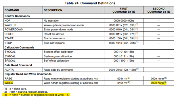
picture of where I send the command to send the data of the ADC:
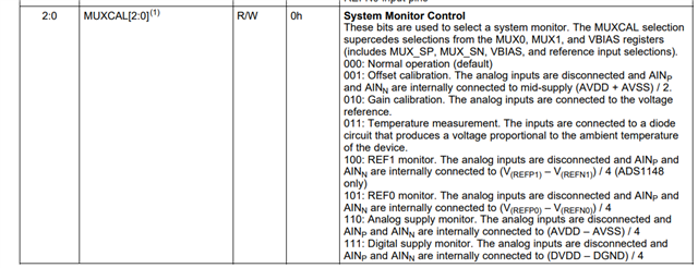
picture of where I select the MUX:
my schematic of the ADS1148: