This thread has been locked.

If you have a related question, please click the "Ask a related question" button in the top right corner. The newly created question will be automatically linked to this question.

AFE4490: Noise present on SPO2 waveform - reg

Part Number: AFE4490

Tool/software:

Hi Team,

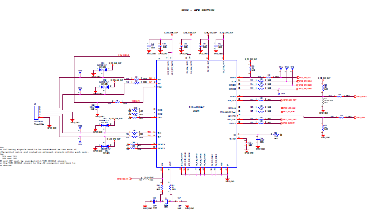
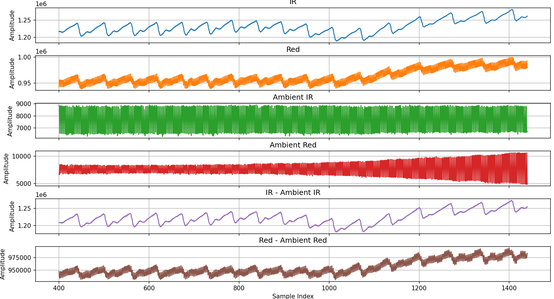
We are using the AFE4490 IC in our customized board and have observed noise on the SpO2 waveform.

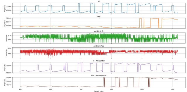
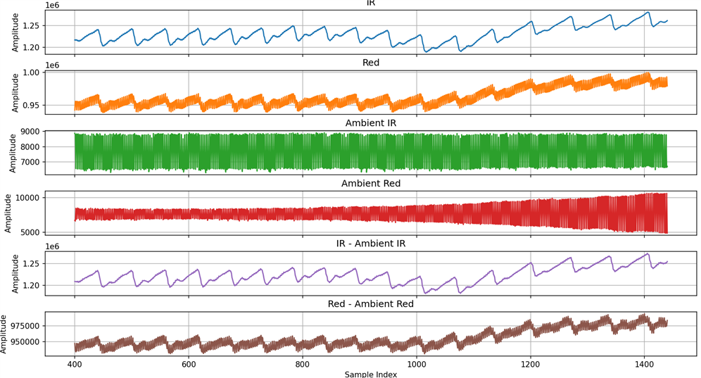
When the probe is connected to the EVM board, the waveform looks clean, but when connected to our custom board, the waveform appears noisy.

For your reference, I’ve attached the waveform screenshots.

Kindly review and provide your suggestions to resolve this issue.

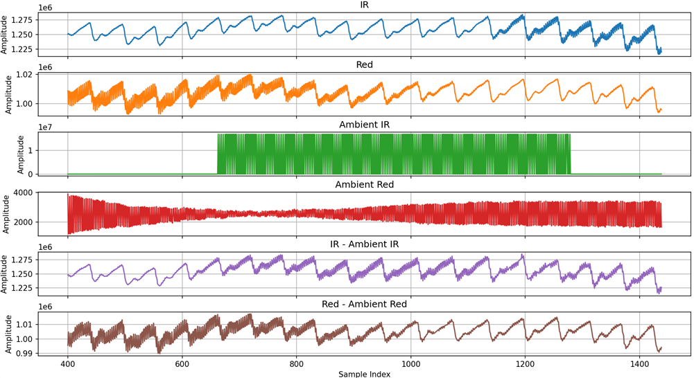
EVM Board with ST Board(Same probe):

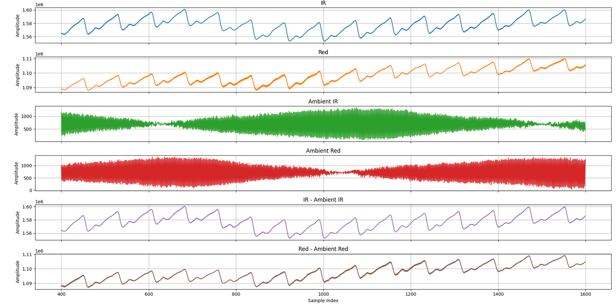
Customized Board with ST Board(Same probe):

  • Hello Sneha,

    Thank you for your post. A couple of questions:

    1) Are you using the same register settings on both the EVM and the custom board?

    2) Would you be willing to share the schematic for your custom board?

    Regards,
    Payton

  • Hi Payton,

    Thanks for the reply.

    1. Yes same register settings used

    2. Attaching the image of the schematic for your reference.

    Waiting for your response.

    Thanks!

  • Hi Team,

    We have connected both our customized board and the EVM board to the Variscite i.MX8M Mini board and tested them using the same probe.

    The noise levels observed on both the custom board and the EVM board appear to be similar. Is the waveforms are correct?

    Attached are the waveforms for your reference.

    EVM Board with imx8M Mini board(using same probe):

    Custom Board with imx8M Mini board(using same probe):

    Kindly give your suggestions to resolve the issue.

    Thanks!

  • Hello Sneha,

    I apologize for the delay.

    The schematic you sent, while blurry, doesn't show anything of concern, and the waveforms look reasonable. However, it looks like noise may be being coupled to the PPG signal, which is especially visible in the "Red" LED data.

    1) What register configuration settings are you using?

    2) Are you using any filtering to account for power line noise coupling to the system?

    Regards,

    Payton

  • Hi Payton,

    Attaching the schematics for your reference.

    1. Values of the registers from 0x01 to 0x1D are updated as per the GUI low level configuration for 100Hz.

    [0x00], CONTROL0 = 0x000000 /*0x000000 = 0 for 100Hz*/
    [0x1D], PRPCOUNT = 0x009C3F /*0x009C3F = 399999 for 100Hz*/
    [0x01], LED2STC = 0x007580 /*0x007580 = 300000 for 100Hz*/
    [0x02], LED2ENDC = 0x009C3E /*0x009C3E = 399998 for 100Hz*/
    [0x03], LED2LEDSTC = 0x007530 /*0x007530 = 300000 for 100Hz*/
    [0x04], LED2LEDENDC = 0x009C3F /*0x009C3F = 399999 for 100Hz*/
    [0x05], ALED2STC = 0x000050 /*0x000050 = 80 for 100Hz*/
    [0x06], ALED2ENDC = 0x00270E /*0x00270E = 9998 for 100Hz*/
    [0x07], LED1STC = 0x002760 /*0x002760 = 10080 for 100Hz*/
    [0x08], LED1ENDC = 0x004E1E /*0x004E1E = 19998 for 100Hz*/
    [0x09], LED1LEDSTC = 0x002710 /*0x002710 = 10000 for 100Hz*/
    [0x0A], LED1LEDENDC = 0x004E1F /*0x004E1F = 19999 for 100Hz*/
    [0x0B], ALED1STC = 0x004E70 /*0x004E70 = 20080 for 100Hz*/
    [0x0C], ALED1ENDC = 0x00752E /*0x00752E = 29998 for 100Hz*/
    [0x0D], LED2CONVST = 0x000006 /*0x000006 = 6 for 100Hz*/
    [0x0E], LED2CONVEND = 0x00270F /*0x00270F = 9999 for 100Hz*/
    [0x0F], ALED2CONVST = 0x002716 /*0x002716 = 10006 for 100Hz*/
    [0x10], ALED2CONVEND = 0x004E1F /*0x004E1F = 19999 for 100Hz*/
    [0x11], LED1CONVST = 0x004E26 /*0x004E26 = 20006 for 100Hz*/
    [0x12], LED1CONVEND = 0x00752F /*0x00752F = 29999 for 100Hz*/
    [0x13], ALED1CONVST = 0x007536 /*0x007536 = 30006 for 100Hz*/
    [0x14], ALED1CONVEND = 0x009C3F /*0x009C3F = 39999 for 100Hz*/
    [0x15], ADCRSTSTCT0 = 0x000000 /*0x000000 = 0 for 100Hz*/
    [0x16], ADCRSTENDCT0 = 0x000005 /*0x000005 = 5 for 100Hz*/
    [0x17], ADCRSTSTCT1 = 0x002710 /*0x002710 = 10000 for 100Hz*/
    [0x18], ADCRSTENDCT1 = 0x002715 /*0x002715 = 10005 for 100Hz*/
    [0x19], ADCRSTSTCT2 = 0x004E20 /*0x004E20 = 20000 for 100Hz*/
    [0x1A], ADCRSTENDCT2 = 0x004E25 /*0x004E25 = 20005 for 100Hz*/
    [0x1B], ADCRSTSTCT3 = 0x007530 /*0x007530 = 30000 for 100Hz*/
    [0x1C], ADCRSTENDCT3 = 0x007535 /*0x007535 = 30005 for 100Hz*/

    [0x00], CONTROL0 = 0x000000 /*0x000000 = 0 for 100Hz*/
    [0x23], CONTROL2 = 0x020000 /*0x020000 = 131072 for 100Hz*/
    [0x20], TIAGAIN = 0x00C006 /*0x00C006 = 49158 for 100Hz*/
    [0x21], TIA_AMB_GAIN = 0x004006 /*0x004006 = 16390 for 100Hz*/
    [0x22], LEDCNTRL = 0x011414 /*0x011414 = 70676 for 100Hz*/
    [0x1E], CONTROL1 = 0x000107 /*0x000107 = 263 for 100Hz*/

    2. Are you using any filtering to account for power line noise coupling to the system? No. Attaching the power section for your reference.

    Thanks!

  • Hi Sneha,

    Your waveforms look correct to me. It does look like there is some 50/60Hz noise coupling into the PPG waveform -- this noise is from the power line frequency of surrounding power, like wall outlets and major electronics that operate at that frequency. This noise can be filtered out with a 50/60Hz notch filter.

    Regards,

    Payton

  • Hi Payton,

    Could you please confirm whether the filtering is implemented in hardware or software?

    If it's a hardware filter, kindly share the notch filter design used for the AFE4490 circuit.

  • Hi Sneha,

    The notch filter can be implemented in either software or hardware. We do not have an existing notch filter design for the AFE4490, but would be happy to review your schematic if you choose to implement the filter in hardware. Additionally, can you determine whether the noise is coming from the SpO2 cable connection or the AFE4490 circuitry itself? Disconnect the sensor cable from the AFE4490, and see if the data still has a 50Hz/60Hz tone. If that's the case, then instead of implementing a hardware/software filter, you should be able to eliminate the 50Hz/60Hz tone by shielding the cable depending on what works best for your application.

    Regards,

    Payton

  • Hi Payton,

    If we removed the sensor cable from AFE4490 EVM board or customized board, we get the constant data.

  • Hi Sneha,

    If the constant data seen when the sensor is disconnected does not have a 50/60Hz tone, then the noise in the data is likely coming from the sensor and the sensor cable. Shielding the cable should improve the signal output. Additional suggestions can be found here.

    Regards,

    Payton