This thread has been locked.

If you have a related question, please click the "Ask a related question" button in the top right corner. The newly created question will be automatically linked to this question.

ADS127L18: Single Ended to Differential Input Driver Circuit

Part Number: ADS127L18
Other Parts Discussed in Thread: OPA320, ADS8912B, OPA2320

Tool/software:

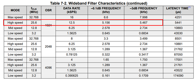
Hello, I am currently working on a signal conditioning circuit where I plan to use the ADS127L18 at the end of the analog signal chain. I plan on configuring the device to be in High-Speed Mode, 25.6MHz clock external, 1024 OSR, Wideband Filter, and both input and reference buffers ON. The Vref will be 2.5V, 1x input range. The input signal will be less than 15kHz.

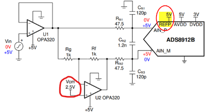
The sensor signal will be single ended going through an instrumentation amplifier first before reaching a driver circuit which then feeds into the ADC. I planned on using two ADA4805 op amps to do single ended to differential conversion as well providing the drive for the ADC input. In the datasheet for the op amp, it shows the circuit to achieve this but doesn't go into much detail as to how to select values for the passive components.

There is also this TI app note "Single-ended to differential using a two op-amp circuit (Rev. A)" that describes the design in more detail with links to videos, but this is for a SAR ADC. The ADC for this post is a delta sigma which I am unsure if I can follow these guidelines for a SAR ADC. If anyone has some advice on this, I would greatly appreciate it. Thanks!

  • Hello James,

    Welcome to the TI E2E community.

    Using OSR of 1024 will limit your input signal bandwidth to a maximum of about 5.5kHz.  If this is not enough bandwidth for your application, then you will need to use a lower OSR (higher data rate) setting.

    The circuit in the application note that you refer to will work well if used with the ADS127L18.  However, the input voltage will be limited from 1.25V to 3.75V when using a 2.5V reference. 

    If you only need THD performance of -100dB or higher, then you can also operate the ADC in a pseudo-differential configuration.  In this configuration, you can tie the AINN to Vref=2.5V, and then use a single buffer amplifier such as OPA320 to operate from 0.1V to 4.9V input.

    Regards,
    Keith Nicholas
    Precision ADC Applications

  • Hi Keith,

    Thanks for the reply, I realized I made a mistake in my initial post with my configurations, the OSR will actually be 512, not 1024.

    And as for the pseudo diff operation, I did not know about that setup, I will look into that to see if that level of THD is acceptable.

    Lastly, for the input range being limited to 1.25V to 3.75V, I'm not sure I understand why that is the case. In the app note, they seem to be using a 2.5V ref as well yet their input range is 0.1-4.9V:

    Thanks for helping me with this, Keith!

  • Hello James,

    If using OSR of 512, then the input filter will limit signal frequency to about 10.9kHz.  Any input signal higher in frequency will be rejected by the digital filter.

    Yes, I meant to add to my original post if you want to use the single-ended to differential circuit as shown over the maximum input range, then you need to increase the ADS127L18 reference voltage to 5V, similar to the ADS8912B used in the circuit.  You will then get an input range of 0.1V to 4.9V in this case.

    Regards,
    Keith

  • Ah ok, I see. I was getting mixed up with the input range of the ADC. I thought since it was a differential input, your reference voltage only needs to be half of what you want your input voltage range to be, i.e., Vref = 2.5V for a desired Vinput = 0-5V in my case. I see now however that regardless of the signal type, differential or single ended, the Vref is what sets the input range of the signal as the ADC is measuring the ratio of the input to the Vref level.

    One additional detail that I overlooked is that the ADA4805 is only rail-rail output but not input. So with a 5V supply, my input range for the entire circuit is limited to a maximum of 4V (from datasheet). So unless I increase my voltage supply, would you recommend switching the op amps to a RRIO part, maybe even the OPA320 used in the app note pictured above? Thanks again!

  • Hi James,

    The OPA320 will support 0.1V to 4.9V with a single 5V supply.  This is a limitation of the amplifier output (it can go nearly all the way to the rail, within a few mVs, but the linearity/offset is not maintained).  Another nice feature of OPA320 is the absence of crossover distortion.  You may not notice this effect for DC  input levels, but if you are trying to capture a sinewave, crossover distortion of most RRIO amplifiers will be significant.

    The below TI Precision Labs video under Low Distortion Design - Input Stage discusses this issue in more detail.

    https://www.ti.com/video/series/precision-labs/ti-precision-labs-op-amps.html#

    For a standard opamp, the OPA320 is one of the amplifiers we recommend for use as an ADC driver, including the ADS127L18.  Since you need two of these for single->differential, the dual OPA2320 is the recommended device.

    Regards,
    Keith