This thread has been locked.

If you have a related question, please click the "Ask a related question" button in the top right corner. The newly created question will be automatically linked to this question.

ADS127L11: REG_ERR Flag when REG_CRC enabled

Part Number: ADS127L11

Tool/software:

I am currently having trouble enabling the REG_CRC bit. When I have the bit enabled, I am always receiving the REG_ERR flag.

I was able to enable the SPI_CRC and use the SPI transactions successfully without getting a SPI_ERR flag but seem to be having more of an issue using the register CRC feature.

Assumptions:

The datasheet says to calculated registers 0x00 to 0x01 with registers 0x04 to 0x0E. I am assuming I am to calculate the crc of all of the bytes in order from 0x00 to 0x0E (omitting 0x02 and 0x03). I am also assuming that the crc init should be 0xFF as that is what the SPI crc calculation requires. I am also assuming that this check should be performed after all of the registers have been set.

After all the registers have been set, I set a 10ms delay before writing to the status register to attempt to clear the REG_ERR flag. However, the error flag is still present.

To attempt to simplify the problem, can someone provide the expected value to place in this CRC field? If I set all values to default except CONFIG4 register, what should the expected CRC be?

uint8_t reg_val[13] = {

0x00, // Address 0x00 for DEV_ID

0x00, // Address 0x01 for CONFIG4, based on read REV_ID

0x00, // Address 0x04 for CONFIG4

0x00, // Address 0x05 for CONFIG4

0x00, // Address 0x06 for CONFIG4

0x00, // Address 0x07 for CONFIG4

0x02, // Address 0x08 for CONFIG4, setting the REG_CRC bit

0x00, // Start of offset values

0x00,

0x00,

0x40, // Start of gain values, default value per reference manual

0x00,

0x00

};

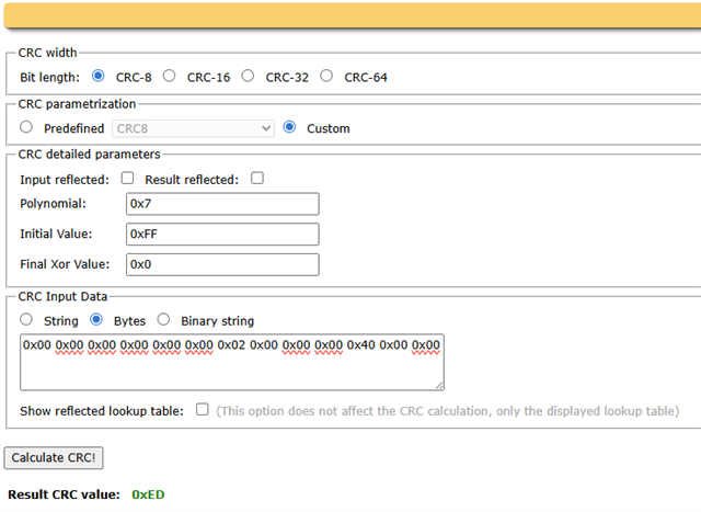
Using the sunshine2k crc tool: Sunshine's Homepage - Online CRC Calculator Javascript

I would expect a valid crc field would be 0xED

I was also having trouble finding examples online of how to implement this register check to confirm I am performing the correct operations. I am assuming TI has a unit test somewhere for this they can provide as a guide.

  • EDIT: I noticed I had a copy/paste error in my comments to state which registers where what. Updated to clarify the register field I am performing the CRC for.

    uint8_t reg_val[13] = {

    0x00, // Address 0x00 for DEV_ID

    0x00, // Address 0x01 for REV_ID, based on read REV_ID

    0x00, // Address 0x04 for MUX

    0x00, // Address 0x05 for CONFIG1

    0x00, // Address 0x06 for CONFIG2

    0x00, // Address 0x07 for CONFIG3

    0x02, // Address 0x08 for CONFIG4, setting the REG_CRC bit

    0x00, // Start of offset values

    0x00,

    0x00,

    0x40, // Start of gain values, default value per reference manual

    0x00,

    0x00

    };

  • Hello Dustin,

    Welcome to the TI E2E community.

    It appears you are getting the correct CRC result for the values you entered.  We also include a CRC tool that you can use for the ADS127L11.

    You can launch the online version using the below link:

    https://dev.ti.com/gallery/view/PADC/PADC_Design_Calculator_Tool

    Or if you prefer, you can download a spreadsheet calculator tool that also calculates CRC:

    https://www.ti.com/tool/download/SBAR019

    The only error that I see in your setup is the REV_ID.  I think it has been updated to 0x01 (the version of the ADS127L11 that I have uses 0x01).  Assuming this is the correct REV_ID for the device you are using, then the correct CRC value will be 0xB0.

    Also note that the ADC_ERR status bit is latched.  Once you have the correct CRC value loaded to the ADC, you need to clear this bit by writing a '1' to it (seems a little backwards, but this is how the device operates).  After writing the '1', you should be able to then read back this value, and if everything is setup correctly, you should read '0' for the ADC_ERR status bit.

    Regards,
    Keith Nicholas
    Precision ADC Applications

  • The issue was on my end on how I was initially reading the REV_ID. Your comment on my default values being off were the breadcrumbs I needed. With the proper reading of the REV_ID being 0x02 for my chip I am no longer getting a REG_CRC error.

    Also, that spreadsheet tool provided was great for debug.

    Thanks for the detailed message.