This thread has been locked.

If you have a related question, please click the "Ask a related question" button in the top right corner. The newly created question will be automatically linked to this question.

ADS131M04: ADS131M04 offset calibration CH1_OCAL_LSB & CH1_OCAL_MSB issue

Part Number: ADS131M04

Tool/software:

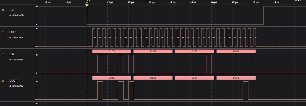
Without input the ADC count getting "64861" at channel '1' in our circuit, so i have applied calibration offset value of "0xFF02E3" at channel '1' in CH1_OCAL_MSB & CH1_OCAL_LSB.
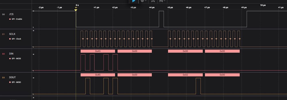
Once done the calibration i have started reading of all the 4 channels ADC value with reasonable input 0.5V, but i am getting '0' for all the 4 channel. 
Is it any sequence or steps to follow to write the calibration value and why other channel values are gone to zero value.

  • Hi Baskar R,

    Was the input of your ADC completely floating or connect a sensor or amplifier when you got "64861" decimal code?  "64861" code means ~9mV that is pretty high.

    For normal offset calibration, you have to short the input on the ADC by setting the MUX bits = 01b in the CHn_CFG register or short your system input. One thing to note is that setting the MUX bits = 01b to short the ADC inputs together will only calibrate the ADC offset. In other words, it will not calibrate out your system offset. So if there are additional offsets in your system, these will not be accounted for in the OCAL procedure, but they will show up in the final measurements.

    Also, averaging more ADC readings to calculate the offset error is recommended when you short the input.

    Finally, the ADS131M04 has a binary two's complement coding scheme (see section 8.5.1.9 in the datasheet). Therefore, if you see a positive offset error from ADC code, no need to convert it to negative value when you write it to the calibration registers. The ADS131M04 corrects for offset errors by automatically subtracting the contents of the OCALn[23:0] register bits in the CHn_OCAL_MSB and CHn_OCAL_LSB registers from the conversion result for that channel before being output.

    BR,

    Dale

  • But usually, the calibration tunning is based on the hardware set-up, so it does not depend on for stand-alone ADC tune.
    Any way i have tried to correct channel -1 offset value with "0xFF02E3" to nullify the ADC output with designed hardware set-up, but other channels are gone to 0 output when i am trying to read the sampled data. Why?

  • Hi Baskar R,

    As I mentioned, the calibration includes system level calibration and chip level calibration. When you short the input of your circuit board, you can get the offset error of your system, you can utilize the calibration registers on the ADC to calibrate out this system offset error.

    If you only wrote the calibration registers of a specific channel, other channels should not be affected because each channel has own calibration registers. If you still have such a trouble, please share your the timing of SPI bus when you program the registers and also your schematic so that I can help to check them.

    BR,

    Dale

  • Hi Dale,

    I have found when it is word length is 24 bit then i am able to write calb register in the ADC fo channel-1.
    And if convert the word length to 16 bit, then i am not able to write & read back the register.
    But the ADC data which i am receiving 16-bit data is perfect for another channels 0,2,3. 

  • Hi Baskar R,

    You should be able to write or read a register in 16-bit word size, the following timing is an example to write and read CH0_OCAL_MSB register in 16-bit word size:

    Write CH0_OCAL_MSB register with 0x0200:

    Read CH0_OCAL_MSB register:

    BR,

    Dale