ADS131M03-Q1: Averaging at Global-chop mode

Part Number: ADS131M03-Q1

Tool/software:

Hi team,

Customer have inquiry on the Global-chop mode.

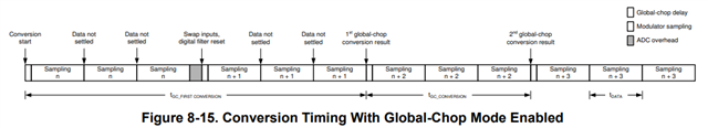
If using Global-Chop Mode, it will measure three sampling (n), three sampling (n+1), three sampling (n+2) times, and so on.
This is the average of the three data obtained. Does this mean that offset correction is applied between the average values?
Or does it use the last value of three samples of sampling (n)?

Best regards,

Hayashi

  • Hi Hayashi,

    SINC3 digital filter takes 3 conversion periods to generate one output where is seen in the last sample of n or n+1, n+2. Chopping takes n sample and n+1 sample and average them together to generate the 1st global-chop conversion result as shown in figure 8-15. Chopping takes n+1 sample and n+2 sample and average them together to generate the 2nd global-chop conversion result, chopping repeats these steps. The device averages the conversion results from two consecutive internal conversions taken with opposite input polarity to cancel the device offset voltage.

    BR,

    Dale

  • Hi Dale,

    Is the explained process only calcurating the device offset voltage? Or it generate the measured voltage minus offset voltage as an output?

    Let me check my understanding is correct about the sampling process.

    FMOD = 4.096 MHz
    OSR = 1024
    Global-chop mode

    Sampling (4.096 MHz)

    ① 1024 point average: OSR

    Sampling (4 kHz)

    ② 3 points average: Global-chop mode (sampling n)

    Sampling (1.33 kHz)

    ③ 2 points average: Global-chop mode (two consecutive internal conversions)

    Output (red line)

    Customer ask it because there are noise on 360Hz, 700Hz, 1.3kHz, 1.7kHz, and it seems that it comes from chop-mode.

    Best regards,

    Hayashi

  • Hi Hayashi,

    Only this device inherent offset voltage is reduced by the global-chop mode. The offset error is automatically calibrated out when the samples are averaged. Offset in the external circuitry connected to the analog inputs is not affected by global-chop mode. 

    It seems the diagram shows frequency domain but the x axis is the number of periods, so it is not clear for me. The customer can turn on or turn off the global-chop mode to see whether the harmonics are related to chopping or not.  

    Could you please help us track and support this opportunity by posting the customer name in the Notes section of the Thread Tracking Toolkit?

    BR,

    Dale

  • Hi Dale,

    What customer wants to know is the frequency response of whole signal processing at ADC. After the first sampling, at ①, the next is 1.33kHz by chop-mode.

    ① 1024 point average: OSR

    WIll it result in noise or harmonics being remained?

    Regards,

    Hayashi

  • Hi Hayashi,

    Global-chop reduced noise and offset error.

    BR,

    Dale

  • Hi Dale,

    Do you have any data to show the example?

    I only see Figure 8-6, which is just after OSR

    Best regards,

    Hayashi

  • Hi Hideki Hayashi1,

    Are you asking what is the filter response when global chop is enabled?

    If yes, please give us a few days to gather this information, we will respond to you next week

    -Bryan

  • Hi Bryan,

    Are you asking what is the filter response when global chop is enabled?

    Yes, exactly.

    Regards

    Hayashi

  • Hi Hideki Hayashi1,

    I was able to put together a spreadsheet that can calculate the frequency response, but I am unable to share this document because of TI internal policies.

    Can the customer provide the following information and I can provide the plot?

    • ADC clock speed
    • power mode (see CLOCK register)
    • OSR (see CLOCK register)
    • Global chop delay (see GLOBAL_CHOP_CFG register)
    • maximum frequency for the plot?

    -Bryan

  • Hi Brian,

    We have NDA with customer, is it not enough for providing a spreadsheet?

    Customer'll answer them, but they have a questions as below. Please kindly support to make customer clear understandings.

    Q1. Why does Fig 8-5 and Fig 8-7 filter response are different? What is the different condition?

    Customer uses OSR = 1024, can customer refer Fig 8-7?

    Q2. Is it able to understand the chop mode as frequency = 0.33 [Hz] because it averages 3 points?

    Regards,

    Hayashi

  • Hi Brian,

    • ADC clock speed = 8.192MHz
    • power mode (see CLOCK register): does this affect the frequency response?
    • OSR (see CLOCK register): 1024 now, but may use 512, please give me the both results.
    • Global chop delay (see GLOBAL_CHOP_CFG register) = 2
    • maximum frequency for the plot? up to ~10MHz

    Best regards,

    Hayashi

  • Hi Hideki Hayashi1,

    Today is a national holiday in the US, please expect a response to your post in the next 1-2 days. Thanks for your patience.

    -Bryan

  • power mode: 10b = High-resolution(default)

  • Hi Hideki Hayashi1,

    I plotted the response using the settings you provided, see below. I plotted up to 20kHz because the plot would not be very useful out to 10Mhz, see the third plot that shows out to 4.096 MHz. I'm not sure what information you could take away from this plot other than the rejection at fMOD/2

    OSR = 1024

    OSR = 512 (fmax = 20 kHz)

    OSR = 512 (fmax = 4.096 MHz)

    -Bryan

  • Hi Bryan,

    Thank you for your data. Customer was thinking using digital filter inside of ADC, it is enough for low-pass. However, since spectrum around 1.33kHz passes after global-chop, is it recommended to use external analog filter to cut off noise? Customer hope to minimize the design of analog filter.

    Best regards,

    Hayashi

  • Hi Hideki Hayashi1,

    Is the customer trying to reject 1.33 kHz? What frequency is the customer trying to pass?

    -Bryan

  • Hi Bryan,

    Yes, they want reject 1.33kHz. The application is automotive battery current sensor, they don't need higher bandwidth.

    Regards,

    Hayashi