DAC8831: DAC8831 Circuit Consultation

Part Number: DAC8831
Other Parts Discussed in Thread: OPA182

Tool/software:

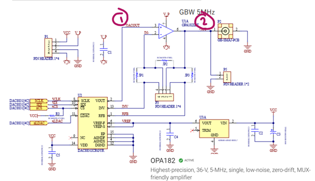
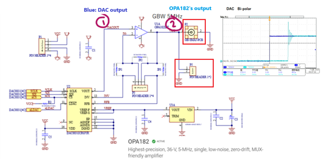
I have assembled a circuit similar to the attached document using the DAC8831. When using bipolar output, there is significant overshoot in the DAC output voltage (oscilloscope waveform: CH2), and I suspect this is due to an issue around the operational amplifier. (The overshoot is not as significant when using unipolar output.)
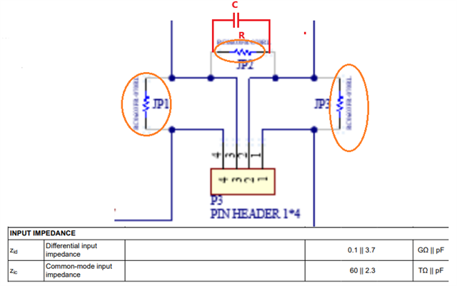
If there are any operational amplifier characteristics or additional components that would be necessary for improvement, could you please provide your advice?
(Currently, the system is configured using the OPA182 op-amps we have on hand.)
Thank you for your attention to this matter.1464.DAC8831.pdf

  • Hello, 

    What is the darker blue signal in the scope plots? Is the lighter blue line the DAC output directly, or the OPA182 output? I assume the OPA182 output. It looks like the op amp is unstable in the bipolar plot. 

    Are you placing/removing JP1, JP2, and JP3 to switch between the unipolar and bipolar configurations? 

    What are your supply voltages? Are you setting to the DAC to the same code in these two plots? It looks like they are going to the same output voltage which wouldn't be the case if you're using the same code in the two different modes. 

    Best,

    Katlynne Jones

  • Thanks for your reply.

    I will answer each question.

    What is the darker blue signal in the scope plots? Is the lighter blue line the DAC output directly, or the OPA182 output? I assume the OPA182 output. It looks like the op amp is unstable in the bipolar plot. 

    Answer:

    As verification, we acquire the waveform (CH1) from the function generator with AD and output the value to DA (CH2).

    Are you placing/removing JP1, JP2, and JP3 to switch between the unipolar and bipolar configurations? 

    Answer:

    The following changes are being made.
    Unipolar JP2 Short
    Bipolar JP1, JP3 Short

    What are your supply voltages?

    Answer:

    5V.

    Are you setting to the DAC to the same code in these two plots? It looks like they are going to the same output voltage which wouldn't be the case if you're using the same code in the two different modes. 

    Answer:

    Different codes are set. *AD is unipolar.
    Unipolar: DAval = ADval*2;
    Bipolar: DAval = (ADval < (1 << 15)) ? (ADval + (1 << 15)) : (ADval - (1 << 15));

  • Hello,

    output the value to DA (CH2).

    Is this at point 1 or 2 in your schematic? 

    There are a few different supply voltages in your schematic. Are they all 5V? Do you have a negative supply? 

    Best,

    Katlynne Jones

  • Is this at point 1 or 2 in your schematic? 

    →②.

    There are a few different supply voltages in your schematic. Are they all 5V? Do you have a negative supply? 

    →The voltage is V_P = +5V and V_N = -5V (overshoot remains unchanged even at ±12V).

    Best,

  • As additional information, I mentioned earlier that overshoot occurs with short waveforms, and that overshoot does not occur when the rise is gradual. if a short waveform is used, does overshoot still occur?

  • Hi Yuki, 

    I read the thread above, and the issue does not seem to come from DAC in either uni-polar or bi-polar. 

    Are there any capacitive load associated with the marked output nodes, say long cable and/or op amp is driving capacitive load directly?

    I mentioned earlier that overshoot occurs with short waveforms, and that overshoot does not occur when the rise is gradual. if a short waveform is used, does overshoot still occur?

    Can you explain what you mean by short waveforms? What is the feedback resistor value above JP2? Can you add a capacitor in parallel with the resistor R (in red) above JP2? The value C will limit the BW of the OPA182 and stabilize the output circuit.  

    Let us assume the OPA182 need to have 1MHz BW for DAC application, then C = 1/(2*pi*1MHz*) is the value that placed in parallel with R. Please provide resistor values next to JP1, JP2 and JP3. My 2nd guess is that the resistor values somehow interact with parasitic capacitance at JP3 header and created a pole that destabilized OPA182 (OPA182 also has some parasitic capacitance at input, though it is not very large). 

    Also, does the OPA182 power with +/-5Vdc regardless of Uni-polar and Bipolar at DAC?

    Best,

    Raymond