This thread has been locked.

If you have a related question, please click the "Ask a related question" button in the top right corner. The newly created question will be automatically linked to this question.

DAC8760: The DAC8760 has calibration limitations: zero calibration cannot be performed to negative values, and gain calibration cannot be performed to 1.5 times full scale.

Part Number: DAC8760

Tool/software:

The DAC8760 has calibration limitations: zero calibration cannot be performed to negative values, and gain calibration cannot be performed to 1.5 times full scale.

The chip is powered from -15V to +15V, the thermal pad is connected to -15V, and the voltage output range is selected from 0 to 5V.

Zero calibration cannot cause the output to fall below 0V. That is, when the zero calibration data is between 0 and 0x7FFF, the output voltage is between 0 and 2.479V. When the zero calibration data is between 0x8000 and 0xFFFF, the output voltage remains at 0V. Shouldn't it be between 0 and -2.479V?

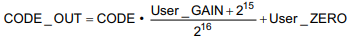
Gain calibration cannot cause the output to exceed 4.96V. That is, when the gain calibration data is between 0 and 0x7FFF, the output voltage is between 2.479V and 4.96V (when the voltage output range is selected from 0 to 5V). When the gain calibration data is between 0x8000 and 0xFFFF, the output voltage remains at 4.96V. Shouldn't it be between 4.96V and 7.5V?

  • DAC Dai,


    The problem that you are seeing is that the user calibration is only a digital implementation, it is not an analog implementation. This is described in detail in the User Calibration section on page 34 of the data sheet. When you set the DAC to 0-5V output range, the output range is still the same. The digital code can be modified by the user_zero and the user_gain, but the output is still limited to be within 0V to 5V. For example here is the user calibration with the CODE_OUT:

    For the CODE value is the value written to the DAC Data Register. This is mathematically modified by the user zero and gain to get a new CODE_OUT value which is what goes to the DAC. If this value is less than 0x0000 or greater than 0xFFFF, then the result is clipped and used as the calibrated DAC data value.

    Below equation 6, the description says "This implementation is purely digital and the output is still limited by the programmed value at both ends of the voltage or current output range. In addition, remember that the correction only makes sense for endpoints inside of the true device end points."


    Joseph Wu

  • Does this mean that calibration can only be performed between -50% and 100%?

    I've made 20 boards, and none of them reach 5.00V, only 4.96V. Does this mean this is a defect in the IC?

    Could you please tell me how to achieve the full-scale 5.00V output?

  • DAC Dai,


    This is not a defect in the device. The calibration is a digital calibration and the output still can't go outside the range that it is set to. If you set the device to the 0-5V range, it can never go outside that value through calibration. If you are currently getting about 4.96V out, it is likely the DAC reference voltage is a little smaller than 5V.

    To get an output value greater than 5V you can still use a higher range and calibrate it lower. Instead of using the 0-5V output range, you can set it to the 0-5V range and use the 10% overrange and then set the calibration to a value a little smaller than the 5/5.5 proportion to get a value that is approximately 5V output. You could also set the range to 0-10V and calibrate it to something close to 1/2. You would lose some resolution, but that would happen through calibration anyway.


    Joseph Wu

  • My design allows users to flexibly select the output range through the menu: 0-5V, 0-10V, -5V-+5V, and -10V-+10V.
    You want me to select a 0-10V output range for a 0-5V application? What if I, as a user, choose 0-10V? This IC clearly cannot output the full range (0-10V). If this were a single issue, there's nothing to say. But all 20 of them are like this. Isn't this a defect? How do you expect us to use it?

    Thank you.

  • dac dai,


    Just to be sure, can you please measure the output voltage at maximum, and then measure the reference voltage. They should match very closely. The reference should be between 4.995V and 5.005V. Let me know what voltage you get.

    Second, you still should be able to reach the output by using the 10% overrange function. Each range 0-5V, 0-10V, ±5V, ±10V all have an overrange function so that you can reach 0-5.5V, 0-11V, ±5.5V, and ±11V.

    You can set this overrange mode with the OVR bit in the control register (address 0x55, DB14).

    If you a little low in voltage, you should be able to set this bit and scale the output back using the gain calibration. This adds +10% of adjustable range, but you should be able to reach your desired full scale.


    Joseph Wu

  • My design outputs both voltage and current simultaneously, with menu-selectable output ranges:
    Voltage output range: 0-5V, 0-10V, -5V-+5V, -10-+10V;
    Current output range: 4-20mA, 0-20mA, 0-24mA;

    When the voltage output range is 0-10V, the output voltage is 9.93V;
    When the voltage output range is 0-5V, the output voltage is 4.96V;
    When the current output is 4-2mA, the output is 3.97-19.86mA;

    The reference voltage is the internal DAC8760, and I measured only 4.96V.
    Enabling the OVR bit and performing gain calibration allows the voltage output to reach full scale, but the output current is insufficient.
    Thanks very much! :)

  • dac dai,


    I'm glad the overrange works for the voltage output. The current output doesn't have a similar overrange. However, you may be able to play with the output range for current in a similar way, but it is a little more complicated. In this setup, you could use the external RSET resistor to set the output current. The current output stage of the DAC is constructed in this way:

    There is a 15kΩ RSET resistor that sets the current output of the DAC. In most cases you would use an internal RSET for the current. However, you could use an external RSET to change the gain. This can be set from Bit 13 in the Control Register. If the current is a little low, a slightly lower resistance would increase the output current. Note that the current scales with this resistance and that any drift in the resistance would be seen as drift in the current.

    I haven't used an external RSET in anything I've worked on, so I'm not sure how the device generates the 4mA current in the 4-20mA current mode. If the 4mA is a pedestal current added to the output current DAC, then the 4mA offset current in the 4-20mA mode might not be adjustable.


    Joseph Wu