This thread has been locked.

If you have a related question, please click the "Ask a related question" button in the top right corner. The newly created question will be automatically linked to this question.

why my TVP5150AM1 can only get the black & white video?

Other Parts Discussed in Thread: TVP5150AM1, TVP5150

Dear,

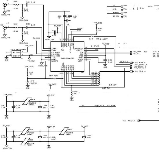
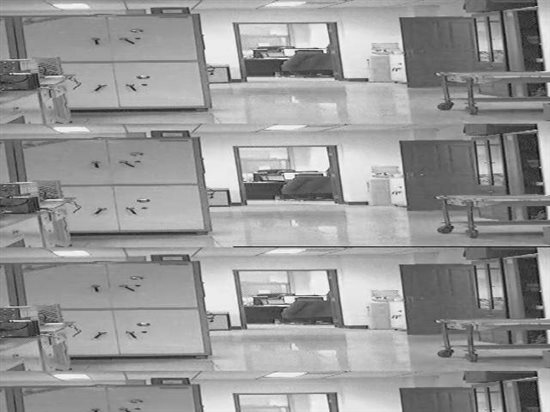
We use TVP5150AM1 for PAL -> BT656 decoder for our ARM9 embedded system.  During the doing my project , I get the CVBS input  into the AIPH1A  and the input resister and capacitance is only be  set to the 37.4 ohm and 0.1uF, the register value is only be set by default too. The YOUT 7 has set a 10K oum rester to pulldown .So this chip work as a slave. Recently we encountered a problem that the video we get from the TVp5150AM1 is  black & white . I  adjust the register 0X03->0X09,0X00-> 0x00,0X07->0X40,0X0D->0X07, the video is only  black & white. By the way the we can get the right value from the register 0x80 , 0x81as the 0x51,0x50.

We check the hardware and software according the TVP5150AM1 pdf file. we can not find any question.

So my questions are,

1. Does the TVP5150Am1 hardware and software which we design have  some  potentially problemhe during usingTVP5150AM1?

2. Does setting the register CVBS input have some questions?

Unfortunately, we cannot identify which one is not right in my design at now.
Thanks in advance.

  • Hi,

    Here is some register value after setting and the hardware design schematic. The output the image remain black & white


    The figure 1 is my schematic. The figure 2 is the capture image after the A/D bypass the TVP5150AM1.


    mx27# insmod tvp5150_cam.ko

    tvp5150_cam: no version for "struct_module" found: kernel tainted.

    tvp5150 driver version 0.0

    /dev/tvin device number is: 252

    Now going to i2c_tvin_init

    int i2c_tvin_attach_adapter

    i2c_tvin_attach_adapter start

    i2c_tvin_attach_adapter end

    I2C addr driver successful

    Now going to tvp5150_i2c_test(void) )

    TVP5150 I2C Test...

    Now going to i2c_tvin_read

    MSB of device ID (0x51): 0x51

    LSB of device ID (0x50): 0x50

    ROM major version (0x82): 0x04

    ROM minor version (0x83): 0x00

    Saturation control (0x0a):0x%

    status2(0x88) = 70

    status2(0x00) = 0

    status2(0x03) = 1

    status2(0x28) = 0

    status2(0x07) = 60

    status2(0x0D) = 47


  • Please try setting bit 5 (GPCL output enable) in REG03h to 1.  If pin 27 is floating, color lock issues can occur if this bit is not set to 1.

    Also make sure the S-video select bit in REG00h is set to 0 for CVBS support.

  • Hi,

    Here is the information after setting the register of the bit 5 (GPCL output enable) in REG03h  and REG00h accordding to your suggestion. But the black & white video remain. I don't know where has some problems.

    The following status information is been read from different registers in tvp5150am1 .

    mx27# insmod /drivers/driver_modules/tvin/tvp5150_cam.ko
    tvp5150_cam: no version for "struct_module" found: kernel tainted.
    tvp5150 driver version 0.0
    /dev/tvin device number is: 252
    I2C addr driver successful
    Now going to TVP5150 I2C Test... and read some some register in tvp5150, that is:
    MSB of device ID (REG 0x51): 0x51
    LSB of device ID (REG 0x50): 0x50
    ROM major version (REG 0x82): 0x04
    ROM minor version (REG 0x83): 0x00
    Saturation control (0x0a): 0x80
    status2(REG 0x88) = 0x76


     which the analog video input AIP1A or AIP1B, read  the (REG 0x00)= 0
    Miscellaneous controls, read the  (REG 0x03) = 1
    force  video register into the PAL standard, read  the (REG 0x28) = 0
    Pedestal is not present on the analog video input signal (default), read the (REG 0x07) = 60
    status2,read the (0x0D) = 47

    Now going to read the regist which the analog video input AIP1A or AIP1B  REG (0x00)= 0
    Now going to read the regist of the Miscellaneous controls REG (0x03) = 29

    And I have a question about the Clock Circuits.  I disigned the external clock circuits in the pin 5 (XTAL1) which can be seen from my schematic figure. Formerly I guess the 3.3 V voltage may be hign,so I input the 14.31818MHz signal from the arbitrary waveform generation which can adjust the voltage of the clock. But the phenomena remain inspite of the different voltage.  And later I guess the EMI circuit of the front may be need adjust , so I adjust the 37.4 resister and 0.1uf capacitance into the 51 and 0.047uf .But all of the experiments can not solve the problem.

    Please tell me where can I improve my hardware design or the software set?

    Thanks

    wang