Other Parts Discussed in Thread: DAC9881EVM, ADS8860, DAC9881
Subject: Communication, Data Logging, and DAC-ADC Sweep Evaluation for DAC9881EVM & ADS8860EVM
Dear Team,
I am evaluating two TI boards:
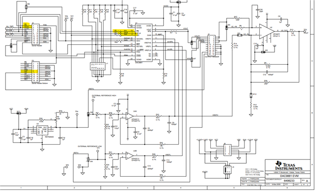
1. DAC9881EVM – I want to know whether this board can be directly communicated with using a standard I²C/SPI adapter (such as Aardvark or similar) If yes, could you please share any documentation or examples for the required connections and protocol details?
2. ADS8860EVM – This comes with the PHI controller board.
Can I connect the PHI board to a PC via USB and use the TI GUI for configuration and data capture?
Is it possible to export the captured ADC sample data from the GUI into Excel, or alternatively, access the converted data directly using Python (for example, through an API or by reading a data log file generated by the GUI)?
The ADS8860 datasheet shows SPI pins such as SCLK, CONVST, etc. Does this device support communication with a standard SPI master (without the PHI board) if I want to directly interface it with another microcontroller or SPI adapter?
3. Evaluation plan – DAC to ADC sweep
I would like to perform a linear voltage sweep test where:
The DAC9881 generates a step voltage output.
The ADS8860 samples the DAC output at each step.
After the ADC captures the value, there is a short wait/delay before the DAC increases to the next step
This process repeats so that ADC digital outputs correspond to each DAC step.
Could you please suggest how to set up communication and proper timing control for this synchronized DAC-to-ADC measurement, preferably using the provided EVMs and available TI tools?
Thanks in advance for your clarification.