ADS8598S: Require solution for Imepdance/Capacitance measurement

Part Number: ADS8598S
Other Parts Discussed in Thread: AFE4300, DAC80516, DAC60516, DAC81416, DAC61416, PGA849, DAC61401, OPA455, OPA462, OPA596, OPA593

Tool/software:

Hi Team,

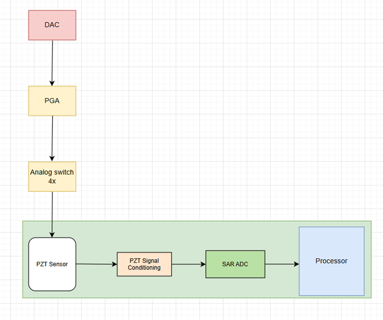
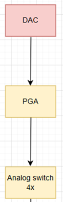
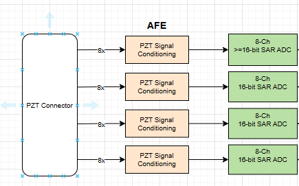
We are designing a data acquisition system that shall comply with the DO-160 military standard. In our system, we will be reading the data from the 32x channel PZT sensor as indicated in the block diagram.

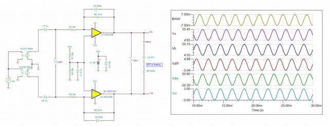
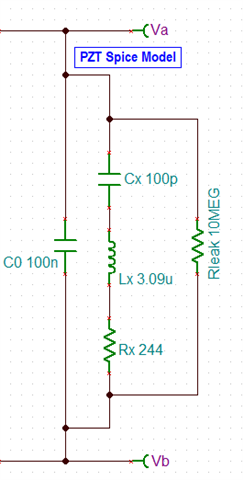
In addition to this, we want to perform impedance/capacitance measurements of each PZT sensor channel by using, maybe, a DAC. Could you please provide a solution for this?

Thanks & Regards,
Sahil Nayak

  • Hello Sahil, 

    Thank you for posting on TI's E2E forum!

    Per your block diagram, the ADS8598S would be a good candidate to enable reading 32 PZT channels. The ADS8598S is an 8-Channel ADC and each channel also has an integrated front end so it could benefit from the configurable gain in the case the input signal is less than the ±5V or ±10V input range of the ADCs. 

    Could you provide more information on what the signal would look after the "PZT Signal Conditioning" block? Or perhaps do you have a schematic we could review to make sure it is optimally configured for the ADS8598S?

    What is the expected type, range, speed of the signal?  Would the full 200kSPS be used/required?  or would a higher sampling rate be required?

    As for the DAC, this device does not have an integrated DAC to help with the impedance/capacitance measurements, but we do have a wide selection of DACs that could be used alongside the ADS8598S.

    Best regards, 

    Yolanda

  • Hi Yolanda,

    We are looking to use a DAC alongside ADS8598S that would help with the impedance/capacitance measurements. Kindly suggest accordingly.

    200ksps sampling rate would be sufficient.

  • Hi Yolanda,

    We are okay to have a solution from any of the following options:

    1. A single-chip solution (ADC + DAC) that helps us to read data from the PZT, as well as measure Impedance/capacitance.

    2. A separate ADC and DAC solution.

    Let us know the best cost-effective solution as per our requirements.

  • Hello Sahil, 

    At this moment we do not have a full solution for a PZT impedance/capacitance measurement, but I could help advise on the ADC part of the solution. Please share relevant parameters of the system related to the ADC. 

    For the DAC, please post on the DAC forum for more help along with relevant DAC parameters 

    Best regards, 

    Yolanda

  • Hi Yolanda,

    During exploration we have found a AD + DAC solution.
    https://www.ti.com/lit/ds/symlink/afe4300.pdf?ts=1755522468411&ref_url=https%253A%252F%252Fwww.ti.com%252Fproduct%252FAFE4300

    Please let us know if this is suitable for our application or not.
    Also, please add a DAC expert in this thread for his/her inputs.

    Thanks & Regards,
    Sahil Nayak

  • Hello Sahil, 

    The AFE4300 is a device that has an integrated DAC and ADC, it also has 4 muxed inputs for voltage and another for current measurement, which would help with impedance testing.. Even then I am still missing information to gauge if this would work for your system. 

    Please share more information on the PZT and the signal conditioning to understand what kind of inputs and outputs are required. Could the specs of the PZT sensor be shared? the expected impedance ranges?

    Best regards, 

    Yolanda

  • Hi Yolanda,

    As of now, we have the input voltage range of the PZT sensor, which is mentioned in the other TI thread that you are assisting.

     RE: ADS8598S: Inquiry regarding right selection and features of ADS8598S ADC 

    Let us know the other specific details required.

    Thanks & Regards,
    Sahil Nayak

  • Hello Sahil, 

    For those ranges it would require a DAC and possibly an added gain stage. The PMU page has some helpful information on this as well as suggestions on devices. 

    For the impedance and capacitance measurements there are some integrated, multi-channel DAC devices that could be very helpful here

    • TSMU818A030 , which can do +/-15V and has a lot of integrated features
    • DAC8775 with some voltage sense capabilities but limited to +/-10V
    • DAC81416 which can go up to +/-20V (or 0 to 40V), but only includes the DACs 

    Best regards, 

    Yolanda

  • Hi Yolanda,

    We already have an ADC ADS8598S in our system for reading data from the sensor. Can this ADC be used alongwith the DACs you suggested for Impedance/capacitance measurement?

    If yes, it would be great if you could explain in a block diagram form to have more clarity and easy understanding.

    I am not sure about DAC8775 and TSMU818A030 of how they could be interfaced for our application requirement.

    I believe DAC81416 can be used with the currently used ADC in our system for Impedance/capacitance measurement.

    A detailed explanation would be really appreciated.

    Thanks & Regards,
    Sahil Nayak

  • Hi Yolanda,

    Do you have any updates to share on this?

  • Hi Yolanda,

    The suggested PMU is very costly.

    Please suggest a cost-effective solution for Impedance measurement.

    Since we already have an ADC in our system, will adding a simple DAC suffice for the Impedance measurement needs?

    Thanks & Regards,
    Sahil Nayak

  • Hello Sahil, 

    I will ask for some help from the DAC team moving forward, they can be  of better help with the DAC selection 

    Best regards, 

    Yolanda

  • Hi Sahil, 

    Can you provide some more details about the DAC requirements for this application? What exactly do you need the DAC to do, and do you have requirements as far as resolution, number of channels interface type, etc? 

    Best,

    Katlynne Jones

  • Hi Katlynne,

    We are looking to use the DAC for impedance measurement purposes.

    Resolution: The input voltage range for each channel of the sensor has an upper bound of ±50 V (100 VPP) and a lower bound of <= ± 1 V ( 2 VPP), so please consider the resolution accordingly.

    Number of channels: We have 32x channels for the sensor. It would be great to have as many high channels as possible.

    Interface type: SPI shall be okay. Any other suggestions if you have?

    Thanks & Regards,
    Sahil Nayak

  • Hi Sahil, 

    We don't have DACs that span that voltage range, so you'll need an external gain stage either way. Resolution determines the voltage step per code. So, if you need a 100Vpp span, a 16-bit DAC would get you a 1.5mV step per code. A 12-bit DAC would get you 24mV per code. Choose whichever fits your application better (higher resolution will come at a higher cost). 

    You can use a unipolar DAC and add an offset to your gain stage to create the bipolar output (Unipolar voltage output DAC to bipolar voltage output circuit (Rev. A)), or use a bipolar DAC. 

    I'd recommend either the DAC80516 (16-bit) or DAC60516 (12-bit) for a high channel count unipolar DAC. Or DAC81416 (16-bit) or DAC61416 (12-bit) for a high channel count bipolar DAC. You can use a high voltage op amp to gain up the DAC output. 

    Both recommendations support SPI. DACx80516 also supports I2C. 

    Best,

    Katlynne Jones

  • Hi Katlynne,

    Thank you for providing your suggestions.

    Since we have 32x channels for the analog sensor, we are planning to implement the Impedance measurement process as per the block diagram mentioned below:

    The portion within the green block is already part of the system. And the rest of the part will be added in order to measure the Impedance.

    DAC: We will be using the Single-channel DAC61401 to generate the excitation signal.

    PGA: We will be using PGA849 to increase the amplitude of the signal as per our requirements.

    Analog switches 4x: We will be using 4x TMUX7612 analog switches and will be connected to the output of the PGA849.

    Since we have 32x channels, we will turn on maybe 8x channels at a time and read the impedance of it through the ADC section (in the green block). 

    Our main concern is that when we turn on 8x channels simultaneously, there should not be any change in the amplitude of the signal received from the output of the PGA849.

    Please confirm if this approach is good to go.

    Thanks & Regards,
    Sahil Nayak

  • Hi Sahil, 

    This approach looks ok, though your device choice may be off. The max output of the DAC61401 is ±20V and the max output of the PGA849 is 36V unipolar or ±18V bipolar. You won't be able to gain the DAC output to ±50V with this PGA. Do you really need programmable gain along with the DAC? You'd still be able to vary the output voltage through the DAC with a fixed high voltage gain stage.

    I'll move this thread to the amplifier team so they can help you select an appropriate amplifier that meets the voltage requirement and the loading requirement to support the 8x channels. 

    Best,

    Katlynne Jones

  • Hi Sahil,

    Resolution: The input voltage range for each channel of the sensor has an upper bound of ±50 V (100 VPP) and a lower bound of <= ± 1 V ( 2 VPP), so please consider the resolution accordingly.

    Could you provide the design information about PZT requirements? I assumed that you are talking about Piezoelectric sensor. 

    If the PZT has to swing up to +/50Vpk, then the op amp's driving options are OPA455 or OPA464. OPA454 may be inadequate to drive the sensor. 

    Here is power amplifier selections.

    https://www.ti.com/product-category/amplifiers/op-amps/power/overview.html

    In addition, please provide the following information.

    1. PZT's driving frequency

    2. PZT load type, equivalent Spice model and/or current requirements

    3. Single or dual supply rails. 

    4. Operating temperature and/or heat dissipation method.

    5. cost?

    If you have other questions, please let me know. 

    Best,

    Raymond

  • Hi Raymond,

    Please see the required details below:

    1. PZT's driving frequency: 500Hz

    2. PZT load type, equivalent Spice model and/or current requirements: Data not available

    3. Single or dual supply rails: The PZT sensor itself generates voltage when under stress.

    4. Operating temperature and/or heat dissipation method: -40 °C to +85 °C with no active cooling required

    5. cost?: Data not available

    Thanks & Regards,
    Sahil Nayak

  • Hi Sahil, 

    Here is a design of piezoelectric driver. It is using OPA462, but you may use OPA455 for your driver, since the output swing is operated up to +/-50Vpk in sinusoidal drive (up to 500Hz). Piezoelectric transducer is typically driving in a floating configuration (better efficiency to drive differentially), though you may drive it to GND as well.  

    https://www.ti.com/lit/ab/sboa502/sboa502.pdf?ts=1757392624445&ref_url=https%253A%252F%252Fwww.google.com%252F

    If you are able to provide the transducer's L, C, R value, I may be able to put together a simulation for you. 

    If you have other questions, please let us know. 

    Best,

    Raymond

  • Hi Raymond,

    Thank you for the information.

    To use this Op-amp, we will need to add a dual rail DC-DC converter that generates  ± 50 V, which can be fed to the Op-amp supply pins.

    Won't it be possible to have this solution using a PGA? By using PGA, we won't need the dual rail DC-DC converter.

  • Hi Sahil, 

    To use this Op-amp, we will need to add a dual rail DC-DC converter that generates  ± 50 V, which can be fed to the Op-amp supply pins.

    If you are able to tell me how much current the piezo transducer (PZT) will source or sink, I may be able to come up with a simulation. For instance, if the PZT can be driven in floating topology(differentially), then ± 50 Vdc + overhead ( ± 5Vdc range) may be good enough. The output of the push-pull driving topology can swing the driver up to 100Vpp.  

    Won't it be possible to have this solution using a PGA? By using PGA, we won't need the dual rail DC-DC converter.

    PGA is not much different from the above design. Yes, you can change the gain settings with PGA, but the amplifier driver section will still require to source/sink in current. The above design has a fixed gain, but you can put in a few switches and make is selectable gains, which is similar to PGA in functionality. PGA typically is more integrated and takes less room. 

    Alternatively, you can make the selectable gains at input and use the differential output drive the PZT device. 

    In either case, you may not require to have dual supply rails in ± 50 Vdc. A single supply rail up to 85Vdc (e.g. OPA596) may be able to drive the PZT, since the transducer is driven differentially. 

    1. PZT's driving frequency: 500Hz

    2. PZT load type, equivalent Spice model and/or current requirements: Data not available

    3. Single or dual supply rails: The PZT sensor itself generates voltage when under stress.

    Based on this, the sinusoidal frequency is 500Hz, up to 100Vpp swing. I need to know what PZT's load characteristics or current level, say < +/- 30mA, then I can simulate one with OPA455. Higher than +/-30mA, we may have to go different route. You may use +/-55Vdc dual supply rails or single ~110Vdc rail. 

    If you have other questions, please let me know. 

    Best,

    Raymond

  • Hi Raymond,

    We don't have the required PZT sensor specifications as of now. I will let you know once we have it.  The only challenge we see here is to have the dual supply rail of ± 50 Vdc in our system, and this requires a bigger space as well. 

    Hi Katlynne,

    Could you please let us know that by verifying which parameter we can say that there will be no loading effect or no attenuation in the analog signal if we follow the suggested approach for impedance measurement? I am re-attaching my approach as I mentioned before.

  • Hi Sahil, 

    The only challenge we see here is to have the dual supply rail of ± 50 Vdc in our system, and this requires a bigger space as well. 

    Here is another driving approach that can save you a power supply, butt the PZT has to be driven differentially or floating. With two OPA596 or single OPA2597 you may be able to drive the drive with a single 50Vdc + overhead. In the simulation, I picked 60Vdc. In practice, 55Vdc in a single supply rail may work for drive a PZT (100Vpp).  

    OPA596 is a lower current power amplifier and it is capable to source or sink up to ±20mA range over temperature. The higher current version is OPA593. It looks like that the project is in concept stage. 

    Here is the simulation. 

    PZT 100Vpp Driver OPA596 09122025.TSC

    Regarding to your following stage, DAC + PGA may take more space.  For instance, you can use DAC to generate modulated high frequency SPWM (say 100kHz or higher) --> Once it is filtered, you can create perfect sinusoidal waveform at 500Hz. I do not know how many gain stages you have. If the application requires multiple gain stages, then PGA may make sense, otherwise, it is not necessary. 

    Please let me know if you want to transfer the query back to DAC team. The query is getting long, I would recommend to start a new one. 

    Best,

    Raymond