This thread has been locked.

If you have a related question, please click the "Ask a related question" button in the top right corner. The newly created question will be automatically linked to this question.

ADS1299-4: Data converters forum

Part Number: ADS1299-4
Other Parts Discussed in Thread: ADS1299, ADS1299EEGFE-PDK

Tool/software:

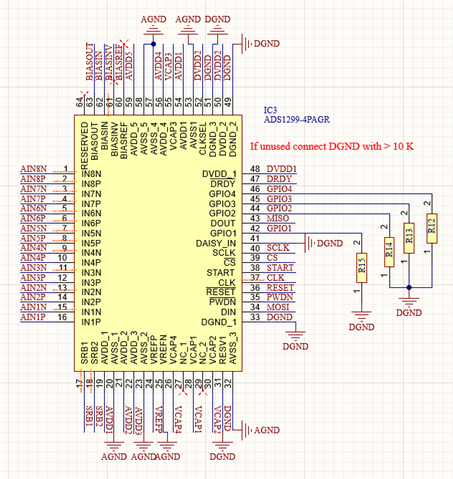
Hello, I have designed an EEG amplifier by using ADS1299-4.

The system has an AD1299 and a Bluetooth chip NRF52840.

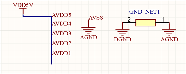
  • Ads1299 analog supply AVdd is 5V

  • Ads1299 analog ground Avss is 0V

  • Ads1299 digital supply DVdd is 3.3V

  • Bluetooth digital supply DVdd is 3.3 V

    the problem I face is that I cannot get required voltages from Vcap 1 - 2 - 3 - 4 pins and Vref

  • Required  Read
    Vcap1  Avss+1.2 0.04V
    Vcap2 (Avdd+Avss)/2 0.3V
    Vcap3 Avdd+1.9 4.19V
    Vcap4 (Vrefp+Vrefn)/2 0.5 V
    Vrefp 2.5 0 V

     
    If someone can help me to understand the source of the problem, that would be great for me.

    Best Regards
  • Hello Atif,

    Thank you for your post.

    Have you checked all AVDD, AVSS, and DVDD pins on the ADS1299 as well? Can you measure the AVDD supply current? As long as /RESET and /PWDN pins are high, VCAP1 should ramp to ~1.2V. VREFP will only show the proper voltage once the reference buffer is enabled.

    I see that you have named the AVDD connections separately - are these all connected together elsewhere in your schematic? Similarly, are AGND and DGND shorted together?

    Regards,

    Ryan

  • Hello Ryan, 
    AVDD pins are separated to read the schematic easily, so they are from the same source. Also, ANGD and DGND are tied with a 0-ohm resistor at a sigle point to reduce noise. 
    AVDD measured 5 V and DVDD measured 3.3 V in PCB. 


    Beforehand I worked with ADS1299EEGFE-PDK and designed my own dewboard to understand the principle of ADS1299. 
    I followed instructions in this forum, and it was functioning. 
    https://e2echina.ti.com/support/data-converters/f/data-converters-forum/207224/faq-ads1298-ads129x-ads129x 

    Below I insert my old dew board. When I power this board, I see 6.9V in Vcap3. Without any trig on RESET and PWDN pins.
    As I understand, Vcap3 should be AVDD + 1.9 when the system gets power.


    It was all okay up to this point. 

    I'm currently experiencing the problem in the next stage, the final product. Everything appears normal at the power input stage.
    When I send a bit message via Bluetooth, I see a very brief logic high on the reset and PWDN pins (power up sequence recommended in ads1299 datasheet), then the Bluetooth shuts down.
    When I power the reset and PWDN pins high with an external source, I can read the voltages I need on the VCAPx pins.

    I know that when I power up the ADS1299 before sending the bit message, I should see 6.9 V on the VCAP3 pin ( but I see 4.2 V).
    I think this is the root of the problem.


    If I miss something please warn me
    Best Regards


  • Hi Atif,

    It seems like the ADS1299 is functioning properly as long as /RESET and /PWDN pins are held high (i.e. disabled).

    When I power the reset and PWDN pins high with an external source, I can read the voltages I need on the VCAPx pins.

    I would check the controller outputs connected to the ADS1299 digital I/O pins during power up and after your initialization command sequence.

    Regards,

    Ryan

  • Hello Ryan, 

    Yes, exactly. It seems that problem is caused by the MCU, but as I know, the Vcap3 pin should be 6.9V with only a power supply.
    I removed the MCU to see if VCAP3 is 6.9V, but it is again 4.2V.

    After seeing 6.9V on VCAP3, the initialization command sequence should follow, then VCAP1 gives 1.2V, and ADS starts to function.

    I need to find why VCAP3 doesn't show 6.9V. 

    If I am wrong at some point please warn me.
    Best Regards

    A.K

  • Hi Atif,

    You may need to complete the power-on reset initialization sequence in order for VCAP3 to show the correct voltage. I believe this is an internally generated boost supply rail that is used by the PGAs. The boost circuit may only become active once the device is fully powered and initialized. 

    VCAP1 should ramp to 1.2V at the same time as the analog supply voltage.

    Regards,

    Ryan