DAC161S997: Load Sharing issue with Dual Channel 4-20mA transmitter when connected with Single Ended PLC inputs

Part Number: DAC161S997

Tool/software:

Team,

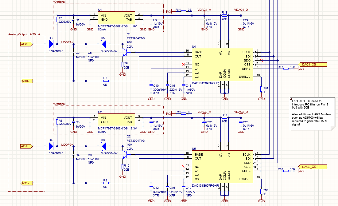
We are using 2 x DAC161S997 for a dual-channel 4-20mA transmitter. Both the DACs share common ground with MCU and there is inbuilt isolation in transmitter circuit.

In the field when both the transmitter outputs are connected to Single Ended inputs of PLC, then it is observed that current for both channels balances to a middle value.

i.e. if

Transmitter CH1 = 6mA

Transmitter CH2 = 8mA

When channels are connected to PLC input AI1 and AI2 respectively then current of both channels balance to middle value of 7mA.

PLC Inputs are Single Ended, Passive (i.e. no Loop Power) and have internal burden resistance of 250 ohms. As per the circuit below both transmitter channels are fed from independent power supply PSU1 and PSU2. 

If only any one channel is connected to PLC then the issue is not observed.

Since the PLC inputs are single ended we are not sure if adding external 2x 4-20mA signal isolators will help in resolving the issue.

The Circuit for DAC is as follows:

  • Manyak,


    The problem comes with the output connection. For the DAC161S997, the output power connections must be isolated from each other. This means that the two power connections cannot be grounded together. The two power supplies must be allowed to float with respect to each other so that the current can be controlled independently.

    Here's the first figure of the data sheet:

    Internal to the device, the current DAC (IDAC) outputs a small current that controls the total loop current. The voltage at the output of the IDAC is at ground from the feedback of the op amp. This current flows through the 80kΩ resistor and is gained by a factor of 2000 through the 40Ω resistor. This total current becomes the current at OUT for the LOOP-.

    The problem is that the total current (I) of the loop comes from the OUT pin. This is at a set voltage from the feedback this voltage is below ground (basically 40Ω × I). Anytime the current is set, this voltage changes in the control of the loop current.

    Going back to your circuit, the two loops may not have a common ground, but they aren't able to float with respect to each other. Because of this, they aren't able to independently set the current in the loop.

    I'm not sure if there's a good way to easily fix this problem. I think you'd need to set up some independent ground for each DAC to allow the control to work. This would require some sort of isolated power and digital communication for each DAC161S997.


    Joseph Wu

  • Hi Joseph,

    Thanks for your explanation!

    Since PLCs generally have Passive Analog inputs it is best that we change our topology to souring type transmitter with per channel isolated floating supply.

    Is there an application note or reference circuit that you can help us with?

  • Mayank,

    I'm afraid I don't have any references on generating an isolated supply. In most cases, the device is used as a singular transmitter on a loop without any devices. 

    You may be able to use the loop power to generate a low voltage isolated supply using a transformer driver. Then this isolated supply could be used to power the device and the microcontroller. 

    Joseph Wu