ADS8167: Instability on REFBY2 and Analog Inputs

Part Number: ADS8167
Other Parts Discussed in Thread: REF2041

Tool/software:

Dear TI Support Team,

We are using ADS8167IRHBT devices in one of our ongoing projects. Our system consists of a Power Board and several other functional boards.

Observation:

On the Power Board, the ADS8167 devices operate without any issue. For example, when monitoring the REFBY2 pin through an analog input channel, the measured value remains stable at ~2.048 V, with only a few mV variation. Also, inputs expected to be at 0 V are read by the MCU as ~7–8 mV.

However, on another board which receives its power and ground connections from the Power Board, we observe significant instability on the ADS8167 devices, even though the same schematic and layout have been applied. When REFBY2 is read over SPI, it fluctuates continuously. Based on the software monitoring graph, the value drops rapidly from ~2.048 V down to ~0.4 V and then returns back. In addition, inputs expected to be at 0 V show readings in the range of 300–800 mV, and sometimes even higher.

Additional Information:

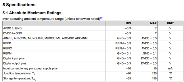
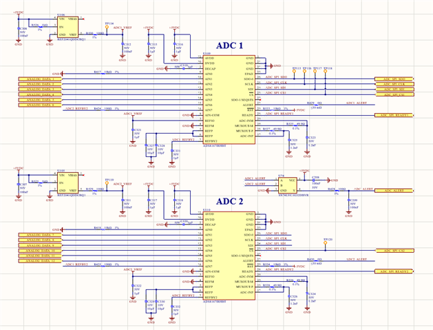
All ADCs are supplied with an external 4.096 V reference (REF2041).

Decoupling capacitors are placed very close to the pins in accordance with the datasheet recommendations (REFP–REFM: 22 µF, REFBY2 and REFIO: 1 µF, VDD: 1 µF).

The problematic PCB is 14-layer, with 4 dedicated GND planes, and power/ground is distributed strongly through multiple pins.

The same topology works stably on the Power Board, but REFBY2 and input readings are unstable on the other board.

We have investigated this issue but have not yet reached a clear conclusion. We would greatly appreciate your technical feedback and guidance. Our schematic is also attached below.

Best regards,

Erhan Kızar

  • Hello,

    We are actively continuing our tests and have obtained the following result:

    When we reduced the SPI read speed from 20 MHz to 1 MHz on the MCU side, we observed a noticeable improvement in data stability. At this speed, the readings are more stable and accurate. However, the level of stability still does not match that of the measurements taken on the power board. In addition, a 1 MHz read speed is unfortunately not sufficient to meet the requirements of our system.

    We look forward to your feedback.

    Best regards,

    Erhan Kızar

  • Hi Erhan,

    Thanks for your patience, I was out of office last week. Let me take a look a this and get back to you tomorrow.

    Best regards,

    Samiha

  • Hi Erhan,

    Thanks again for the detailed post. The behavior you are seeing is definitely strange. In the problem device/board, could you try probing the AVDD, DVDD, and all reference pins and let me know if they are holding stable at the expected values? Additionally, are the SPI signals in both devices connected similarly, that is, nothing is loading the digital signals, right?

    Also, in the problem device, is it possible that the absolute max ratings were ever violated? I ask as this can cause the device to operate unexpectedly.

    Best regards,

    Samiha

  • Hello Samiha,

    In the attached figure, the following measurement results are presented in order:

    • Output voltage of the reference IC,

    • Voltage measured at the ADC reference pin,

    • Voltage obtained from the REF_BY2 pin,

    • Supply voltages applied to the VDD pins.

    Upon examination of these measurements, no anomalies such as voltage drops, rises, or collapses have been detected.

    In addition, the SPI lines of both functional and non-functional ADCs were observed using an oscilloscope, and it was determined that the SDI and CLK signals were nearly identical in both cases.

    Best regards,

    Erhan Kızar

  • Hi Erhan,

    Thanks for sharing. Could you try an A-B-A swap of the ADCs and see if the problem follows the ADC or the PCB?

    Best regards,

    Samiha

  • Hello Samiha,

    We have applied the method you suggested; however, unfortunately, it did not yield any results. In addition, we have encountered the following issue: when reading at 1 MHz, the data from the ADC whose CS signal becomes low first remains stable and consistent, whereas the data from the ADC whose CS signal becomes low later appears fluctuating and unstable. As we know, when reading at more than 1MHz, both devices produce highly erroneous and inconsistent data. In contrast, we have observed that the ADCs on the functioning board operate very stably and as expected at all speeds.

    You mentioned that this issue might be related to the PCB. Could you please elaborate on how we can verify this possibility and what exactly you meant by that?

    Best regards,

    Erhan Kızar

  • Hi Erhan,

    Thanks for the information. I checked with the team and we are wondering if the issue you are seeing is because the REF/2 pin is not driving the input pin correctly, as this is not really what it is designed to do. The 100 ohm resistor on the AIN7 signal path is probably also contributing to this. Could you check if it is really a 100ohm resistor (and not a larger one)? The fluctuations you are seeing on the REF/2 pin may be caused by the kickback from the ADC sampling capacitor. 

    1. Could you try powering up the device, leaving the SPI idle (so the ADC is not converting), and checking if the REF/2 pin is fluctuating or not?
    2. You can try replacing the 100 ohm resistor on the AIN7 input with a 0 ohm resistor/short and resume normal SPI activity. Is the instability improved?

    Best regards,

    Samiha

  • Hello Samiha,

    We removed the 100 Ω resistor that connects the REF/2 pin to the AIN input. When monitoring the REF/2 pin with the oscilloscope, we did not observe any fluctuations. The data read from the AIN input still remains highly unstable. Replacing the 100 Ω resistor with a 0 Ω resistor also made no difference.

    We have not been able to make any progress in resolving this issue yet. We would appreciate your thoughts and recommendations.

    Best regards,

    Erhan Kızar

  • Hi Erhan,

    I see. What about when you power up the ADC and observe the REF/2 rail when the ADC is not converting, ie SPI is held idle (no CS, no SCLK)?

    Best regards,

    Samiha