ADS131M08: SPI Problems Persist (we are on a Raspberry Pi 4 model B)

Part Number: ADS131M08

Tool/software:

Following:

https://e2e.ti.com/support/data-converters-group/data-converters/f/data-converters-forum/1528101/ads131m08-spi-reads-are-inconsistent/5879891#5879891

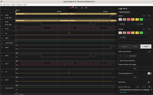
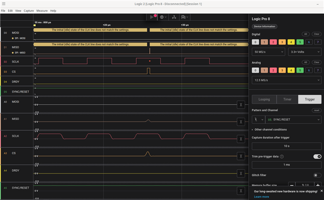
we have slowed the SCLK way down, but are still having problems. If you could please inspect the attached Salae session dump, I want to direct your attention to the first MOSI traffic and the errors denoted there. Somewhere about +25µsec. You will find there and odd red blip amid the SCLK signal, and you will also not a blip in the MISO that is much narrower than the traffic rate. It appears that it might be crosstalk from the CS signal, or are my eyes playing tricks on me? The logic analyzer declares that "The initial (idle) state of the CLK line does not match the settings." Thank you for any wisdom that you can share.Session1.sal.zip

Clark

  • I have zoomed into the anomaly with screen shots. Clearly, the logic analyzer does not like it:

    THANK YOU!

  • Hi Clark,

    I checked your timing:

    1. During the first 50ms period in your timing, you forced /SYNC/RESET signal to low when you were sending SCLKs and /CS to the ADC, and also you were sending 16 SCLKs to the ADC, but the default word length is 24 bits, those operations are definitely wrong.
    2. Starting from 5.9ms in your timing, you sent 20 bytes SCLKs to the ADC in one frame, then went back to 2 bytes (16 SCLKs), then you repeated this sequence between 20bytes and 2 bytes as a frame.
    3. Starting from 53.5ms until 58.8ms, you forced the /SYNC/RESET signal to high, but there are a lot of spikes on the /CS, those spikes definitely messed up the communication between the ADC and your host controller.
    4. After the moment of 58.8ms, you timing went back to 2 bytes (16 SCLKs), you received 0x05FF data on MISO, this is the correct response from the ADS131M08 ADC, this is the STATUS word.

    I double checked the photograph of your test setup in your previous post from the link, you are using so many blue wires and also a bread board to connect the digital SPI and control signals from the ADC EVM board to your host controller board, so I'm not surprised spikes were seen on your /CS signal. I would strongly recommend you:

    • Design a circuit board to combine both your controller and the ADC device to a single circuit board or use short blue wires between the EVM and your controller board without a bread board.
    • Correct your software code and optimize your timing, I already showed my timing in your previous post that can be a reference for you.

    BR,

    Dale

  • Thank you Dale;

    On this one:

    "Design a circuit board to combine both your controller and the ADC device to a single circuit board or use short blue wires between the EVM and your controller board without a bread board."

    We have take delivery of the production boards, and all recent posts concern it, and NOT the EVM. Here are three photos of the production board as it is:

    with logic analyzer connected:

    We will work through your timing suggestions carefully. The CPU is a Raspberry Pi 4, which you can see the end of in the 1st pic I posted above.

  • Hi Clark,

    Thank you for your update. Let me know if you have any further questions.

    BR,

    Dale

  • Mystery solved. The DRDY pin is active before the SYNC/RESET line is released. Therefore installing the ISR before the reset completes generate a massive amount of bogus traffic that clobbers the registers in the app. The lesson: Install ISR after reset completes. Remove before and re-install after every reset, and every SPI communication.

  • Hi Clark,

    Thanks for your update. 

    BR,

    Dale