DAC39J84: Sync Toggling

Part Number: DAC39J84
Other Parts Discussed in Thread: LMK04828

Tool/software:

Hi,

When I am trying the configure the DAC39J84 I am observing my sync signal and
tx_tready signal are toggling. I am configuring the DAC with the following settings:

      sampling rate =   500 MHz,
      linerate           =   5 GSPS,
      DACCLK        =   500 MHz,
     JESD Ref clk  =   125 MHz,
     SYSREF         =   1.953125 MHz,
     LMFS              =   8411,
     K                     =   32

The device clock and SYSREF for the FPGA are given from LMK04828. The device clock for
the DAC (DACCLK) is given from the LO1 output of HMC835. The LO2 output of HMC835 is
given to HMC7043 divider, which has same frequency as that of LO1, from which the DAC SYSREF
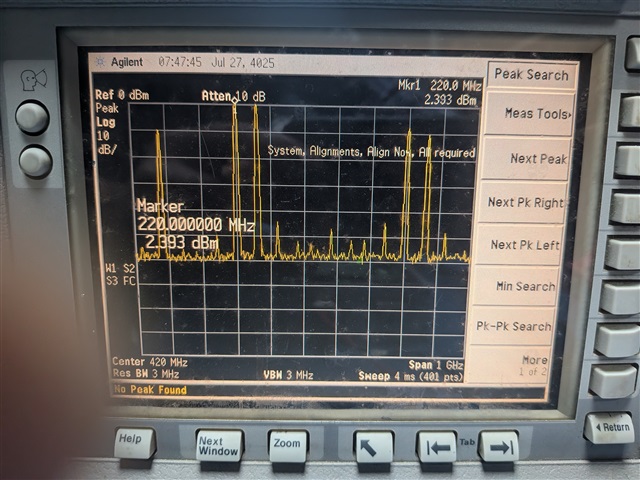
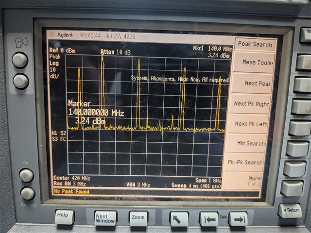
is generated. I have performed the NCO test for SYSREF and observed that the SYSREF is being
generated correctly i.e.I can observe multiple peaks.

The following registers are written for configuring the DAC -

ADDR    DATA
0x00    0x001C
0x01    0x0800
0x02    0x2082
0x03    0xF080
0x04    0x00FF
0x05    0xFF0D
0x06    0xFFFF
0x07    0x0000
0x08    0x0000
0x09    0x0000
0x0A    0x0000
0x0B    0x0000
0x0C    0x0400
0x0D    0x0400
0x0E    0x0400
0x0F    0x0400
0x10    0x0000
0x11    0x0000
0x12    0x7000
0x13    0x7000
0x14    0x0000
0x15    0x0000
0x16    0x4000
0x17    0x0000
0x18    0x0000
0x19    0x4000
0x1A    0x0020
0x1B    0x0000
0x1E    0x1111
0x1F    0x99C0
0x20    0x8888
0x22    0x1B1B
0x23    0x01FF
0x24    0x0020
0x25    0x2000
0x26    0x0000
0x2D    0x0001
0x2E    0xFFFF
0x2F    0x0004
0x30    0x0000
0x31    0x7030
0x32    0x0700
0x33    0x7FC8
0x34    0x0000
0x3B    0x0800
0x3C    0x9028
0x3D    0x0088
0x3E    0x0108
0x3F    0x0000
0x46    0x0044
0x47    0x190A
0x48    0x31C3
0x49    0x5500
0x4A    0xFF1E
0x4B    0x1F00
0x4C    0x1F07
0x4D    0x0300
0x4E    0x0F6F
0x4F    0x1CC1
0x50    0x0000
0x51    0x00DF
0x52    0x00DF
0x53    0x0000
0x54    0x00FF
0x55    0x00FF
0x56    0x0000
0x57    0x00FF
0x58    0x00FF
0x59    0x0000
0x5A    0x00FF
0x5B    0x00FF
0x5C    0x1155
0x5E    0x0000
0x5F    0x0123
0x60    0x4567
0x61    0x0003
0x64    0x0000
0x65    0x0000
0x66    0x0000
0x67    0x0000
0x68    0x0000
0x69    0x0000
0x6A    0x0000
0x6B    0x0000
0x6C    0x0000
0x6D    0x0000
0x6E    0x6A70
0x6F    0x0325
0x70    0x076F
0x71    0x01D6
0x72    0x016E
0x73    0x5974
0x74    0xD6D8
0x75    0x7000
0x76    0x6A70
0x77   0x0325
0x78   0x076F
0x79   0x01D6
0x7A   0x016E
0x7B   0x5974
0x7C   0xD6D8
0x7D   0x7000
0x7E    0x0000
0x7F    0x0000


With these settings I am able to observe the sync and ready signals are toggling. I have verified
all the registers mentioned in the datasheet under " Initialization Set up" section. Is there any register
that needs to be configured or any other setting that needs to be considered to establish a stable link ?

Regards

P. Anirudh Reddy

  • Hi Anirudh,

    Not sure why SYNC toggles. We have not seen it do that before.

    Is it toggling at the sysref frequency by chance?

    Do you have some bit unmasked and each sysref pulse is asserting CGS restart?

    Regards,

    Rob

  • Hi Rob,

    The sync toggling issue has been resolved when I changed the register 0x49 to 0x0000 which is the JESD link configuration setting. 

    Now to check the DAC output, I am configuring the NCO to generate the 280 MHz signal which is given as one of the inputs to the mixer and giving a constant signal like 7F7F7F7F as another input to the mixer. The corresponding registers to enable the mixer, NCO and Frequency control word are written. The sampling rate, clocks and other parameters are same as mentioned above i.e. they are:

         sampling rate = 500 MHz,

          linerate = 5 GSPS,

          DACCLK = 500 MHz,

         JESD Ref clk = 125 MHz,

         SYSREF = 1.953125 MHz,

         LMFS = 8411,

         K = 32

    I can observe the output as 220 MHz due to aliasing. I can also observe the image frequencies.

    When I try to enable the 2x interpolation, I can see the output as 140 MHz. I am enabling the 2x interpolation by writing the 0x00 register with data 0x011C. Generally when 2x interpolation is enabled, the sampling rate will be doubled and I need to get the output as 280 MHz. But this is not the case with my output.

    Am I missing any register or will there be any change in the DAC input rate and DACCLK when interpolation is enabled such that I can get the desired output.

    Regards 

    P. Anirudh Reddy

  • Hey Anirudh, 

    Are you also doubling the clock rate of the DAC when you change the interpolation to 2x? Interpolation is what determines the rate between the input data and the output data. So simply increasing the interpolation from 1x to 2x will just cause the input rate to be halved. Typically changing the interpolation also requires adjusting the SERDES settings as the input rate changes with interpolation. 

    Regards, 

    Matt 

  • Hi Matthew,

    After doubling my DACCLK (input data rate) to 1000 MHz, I am able to get the correct output of 280 MHz. 

    Now I am trying to feed the DAC with IQ samples. The following parameters are set to implement this configuration :

                   LMFS         =    8212

    Sampling Frequency =  500 MHz

                    DACCLK   =    1000 MHz

                   SYSREF    =     1.953125 MHZ

            JESD Ref_Clk  =  125 MHz

                    linerate     =    5 GSPS

               Interpolation  =    2x

    I am generating the IQ samples for input frequency 250 MHz using Matlab by setting the sampling frequency to 1000 MHz (as interpolation is enabled).
    I am writing the following set of registers to configure the DAC:

         Addr     Data
    	 0x00    0x011C
    	 0x01    0x0800
    	 0x02    0x2082
    	 0x03    0xF380
    	 0x04    0x00FF
    	 0x05    0xFF0D
    	 0x06    0xFFFF
    	 0x07    0x0000
    	 0x08    0x0000
    	 0x09    0x0000
    	 0x0A    0x0000
    	 0x0B    0x0000
    	 0x0C    0x0400
    	 0x0D    0x0400
    	 0x0E    0x0400
    	 0x0F    0x0400
    	 0x10    0x0000
    	 0x11    0x0000
    	 0x12    0x0000
    	 0x13    0x0000
    	 0x14    0x0000
    	 0x15    0x0000
    	 0x16    0x0000
    	 0x17    0x0000
    	 0x18    0x0000
    	 0x19    0x0000
    	 0x1A    0x0020
    	 0x1B    0x0000
    	 0x1E    0x1111
    	 0x1F    0x99C0
    	 0x20    0x0800
    	 0x22    0x1B1B
    	 0x23    0x01FF
    	 0x24    0x0020
    	 0x25    0x4000
    	 0x26    0x0000
    	 0x2D    0x0001
    	 0x2E    0xFFFF
    	 0x2F    0x0004
    	 0x30    0x0000
    	 0x31    0x7030
    	 0x32    0x0700
    	 0x33    0x7FC8
    	 0x34    0x0000
    	 0x3B    0x1800
    	 0x3C    0x9028
    	 0x3D    0x0088
    	 0x3E    0x0108
    	 0x3F    0x0000
    	 0x46    0x0044
    	 0x47    0x190A
    	 0x48    0x31C3
    	 0x49    0x0000
    	 0x4A    0xFF1E
    	 0x4B    0x1F00
    	 0x4C    0x1F07
    	 0x4D    0x0300
    	 0x4E    0x0F6F
    	 0x4F    0x1CC1
    	 0x50    0x0000
    	 0x51    0x00DF
    	 0x52    0x00DF
    	 0x53    0x0000
    	 0x54    0x00FF
    	 0x55    0x00FF
    	 0x56    0x0000
    	 0x57    0x00FF
    	 0x58    0x00FF
    	 0x59    0x0000
    	 0x5A    0x00FF
    	 0x5B    0x00FF
    	 0x5C    0x1155
    	 0x5E    0x0000
    	 0x5F    0x0123
    	 0x60    0x4567
    	 0x61    0x0003
    	 0x64    0x0000
    	 0x65    0x0000
    	 0x66    0x0000
    	 0x67    0x0000
    	 0x68    0x0000
    	 0x69    0x0000
    	 0x6A    0x0000
    	 0x6B    0x0000
    	 0x6C    0x0000
    	 0x6D    0x0000
    	 0x6E    0x6A70
    	 0x6F    0x0325
    	 0x70    0x076F
    	 0x71    0x01D6
    	 0x72    0x016E
    	 0x73    0x5974
    	 0x74    0xD6D8
    	 0x75    0x7000
    	 0x76    0x6A70
    	 0x77    0x0325
    	 0x78    0x076F
    	 0x79    0x01D6
    	 0x7A    0x016E
    	 0x7B    0x5974
    	 0x7C    0xD6D8
         0x7D    0x7000


    I am feeding only IQ data to the DAC and the mixer and NCO are disabled. When I observed the output in the spectrum, I cannot see any peak.

    Later I have enabled the mixer and written the NCO frequency word to generate 0.1 MHz frequency. So one of the inputs to the mixer will be the IQ data
    and the other input will be the 0.1 MHz. Now I can observe the peak at 250 MHz in the spectrum.

    Can't I get the single tone output without enabling the NCO by giving only the IQ data or do I need to configure any other register for that ?