ADS127L21: Separate or Joined Ground Planes for Continuous SPI Read

Part Number: ADS127L21

Tool/software:

Hello ADC team,

We are building a test board for the ADS127L21 and are trying to decided if we should separate or join the analog and digital grounds.

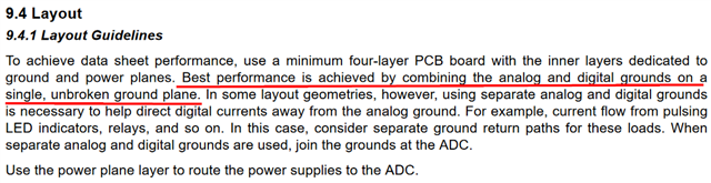
I thought it was common practice to separate the analog and digital grounds. However, the datasheet says the best performance is to combine them unless fluctuations are expected.

My use case is to continuously retrieve SPI data from the ADS127L21. Would this cause noise in the analog supply that would warrant me to separate the grounds? Or still not necessary and I can combine? There is no other switching or disturbance on the board. It is a simple board: the ADC gets the voltage data from a temp sensor then sends it to a MCU through SPI.

Side note: we could not find the ADS127L21 in the Altium library and had to use a similar part number for the schematic drawing--is there not a model available?

Looking forward to your advice.

Thank you,

Jennifer

  • Hello Jennifer,

    As long as the digital signals and analog signals are separated on the board layout and do not directly cross over each other on different PCB layers, then either a solid ground plane or split plane can be used from a noise perspective.  If you can use a solid ground plane, you will typically have better ESD/EOS performance, which is why we recommend the solid ground plane in most use cases.

    However, you can use split planes and still get good performance.  You must use split planes if operating the ADC analog supply with bipolar +/-2.5V supplies.  The evaluation board supports bipolar supplies, so the AVSS and DGND are on separate planes and we are able to get datasheet noise performance.

    I will reach out to you via email regarding the Altium library.

    Regards,
    Keith Nicholas
    Precision ADC Applications