Other Parts Discussed in Thread: ADS1261
Tool/software:
Hello experts,
Currently my customer is reviewing our ADS1261 for their industrial robot control module.
Right now they have evaluated with 1.2ms period, which is slower, now they are trying to test with 100us period, sending rising edge to start pin every 100us to conv. start.
They had a few questions on this, could you please share your feedback?
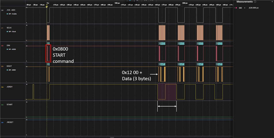
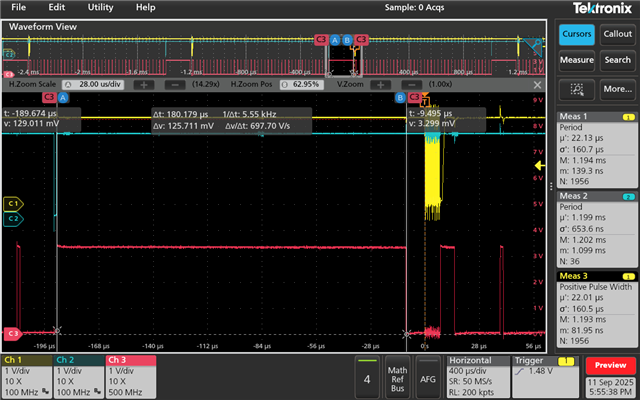
1. When they send rising edge every 100us to start pin they have no feedback from DRDY, but if they do 200us, DRDY pin goes high afterwards for about 180us. They set the DR register to every 25us, so they thought the DRDY pin would only last HIGH for 180us, is there a reason why it would still be 180us? Can they shorten this 180us with another register setting? Please find waveform image & their code configuration as below. (Yellow: SPI CLK / Blue: START / Red: DRDY)
2. May I ask, how can customer set ADS1261's conversion speed & SPI speed to a fastest rate?
3. Customer is using an internal clock. To set this to 10.24MHz my understanding is that they should set DR to 40000SPS, and it would automatically be set, would this be correct? Are there any additional register settings that are needed?
4. Is it possible to use continuous mode to set the start signal once at the beginning, and just let the keep doing the data conversion?
Customer's code configuration from #1:
/* Configure INPBIAS register: default settings */
writeSingleRegister(REG_ADDR_INPBIAS, INPBIAS_DEFAULT);
/* Configure PGA register: Single-Ended */
writeSingleRegister(REG_ADDR_PGA, PGA_BYPASS_MASK); // PGA_BYPASS_MASK or PGA_GAIN_1
/* Configure input MUX: Volatage monitor */
uint8_t regData = (INPMUX_MUXP_AIN0 | INPMUX_MUXN_AINCOM);
writeSingleRegister(REG_ADDR_INPMUX, regData);
/* Configure Data Rates and Filter */
uint8_t regData1 = (MODE0_DR_40000_SPS | MODE0_SINC2); // fCLK = 10.24 MHz, 1cycle = 97.66ns
writeSingleRegister(REG_ADDR_MODE0, regData1);
Waveform:
(Yellow: SPI CLK / Blue: START / Red: DRDY)
Thank you in advance for your help and support.