Tool/software:
Good day TI Professionals,
I am attempting to program the ADC_ads7953-Q1 GPIO 0 and GPIO 1 output alarms. I am failing to get the alarms to trigger when i attempt to force them to go high. I attempted to force them high by changing their Low alarm to activated below 0xFFFF and the High alarm to be activated above 0
I am referencing the datasheet
"ADS79xx-Q1 8-, 10-, and 12-Bit, 1-MSPS, 4-, 8-, 12-, and 16-Channel, Single-Ended,Micropower, Serial Interface, Analog-to-Digital Converters" (ADC_TXIIS238478-1) - Section 7.6.
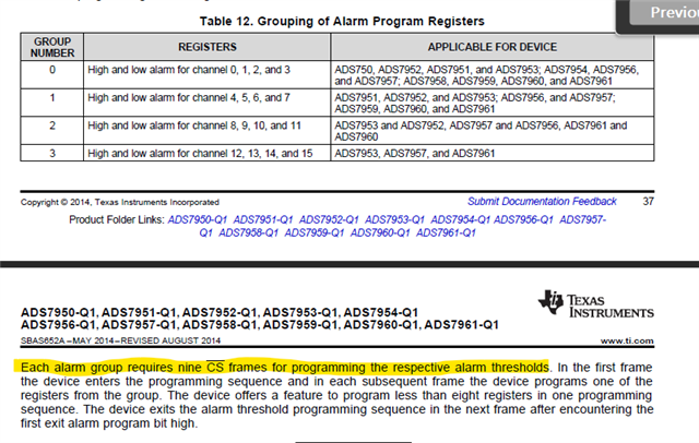
Per the diagrams and tables
I believe the sequence should be:
1. 0x4063 //GPIO Program-Register Settings; GPIO 0 and 1 pins should be outputs
2. 9 CS bar frames
3. 0xF000 // Frame 1 - per table 12 alarm program reigsters group Number is 3
4. 0xE000 //1110 High Alarm for Channel 15 xx00 0000 0000 Frame 2 - I would expect this line to program the GPIO 0 High alarm register to be active when the input in Channel 15 is greater than 0.
5. 0xCFFF //1000 Low Alarm xx11 1111 1111 Frame 2 - I would expect this line to program the GPIO 1 Low alarm register to be active when the input in Channel 15 is less than the Max.
Questions:
Can you confirm I understood the functionality right?
Could you provide me a programmatic example how to set the GPIO 0 alarm high or how to manually trigger the GPIO0 HIGH and GPIO1 LOW alarms?
Thank you!