This thread has been locked.

If you have a related question, please click the "Ask a related question" button in the top right corner. The newly created question will be automatically linked to this question.

TPL0102-EP: Designing with TPL0102-EP

Part Number: TPL0102-EP


Tool/software:

Hello team,
We are planning to use the digital potentiometer TPL0102-EP in one of our products.

The same will be used in the feedback network of a DC DC Converter to adjust the voltage.

RPMA-4.5/OF is the DC DC Converter we are planning to use.

We need an output voltage of +5V to +18V. (1V step)
So the value of the Trim resistor will be 8.57K to 0.91K.

Can you please clarify the following doubts we are having?.

1). Can I use the digipot TPL0102-EP for our application?.

2). What is the maximum allowable current through this digipot?.

3). The tolerance of the digipot is 20%, is there any other device available will low tolerance?.

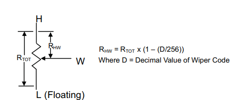
4). In our case we will be using only HA and WA. HA will be connected to TRIM and WA will be connected to the +VOUT of the DC DC Converter. LA, HB, WB and LB will be left floating

5). Is there any problem if we connect the 2 channels of TPL0102-EP in series.

6). Is it possible to get 0E resistance from the digipot (considering wiper resistance).

7).

  • Hello, 

    1) Is -VOUT connected to ground? The TPL has a max voltage rating, but if the terminals will be connected between the 0.6V reference voltage and ground then this should be fine. 

    2) 20mA pulse, 2mA continuous 

    3) All of our digipots have 20% end to end tolerance. Typically, we can use a DAC in place of a digipot for higher accuracy, but it is not clear to me from the RPMA datasheet if this is possible. They don't share how the voltage setting works. Here is an article about how to use a DAC: Voltage Margining and Scaling Circuit with a Voltage Output Smart DAC (Rev. A)

    4) This is fine. You'll be operating in this mode: 

    5) No problem. Connect HA to TRIM, WA to HB, and WB to -VOUT. 

    6) Considering wiper resistance, no. There will always be a series resistance on each pin. 

    Best,

    Katlynne Jones

  • Hello Team,
    Sorry for replying late.

    I was waiting for the updates from the manufacturer of DC-DC Converter.

    We cannot do output voltage adjustment by voltage injection method as the DC-DC Converter is designed for resistors only. "the trim pin is designed for resistor, not voltage injection. If we inject voltage directly, it may not behave predictably and could even damage the trim circuit.".

    The voltage and current at the trim pin will be "The current through the resistor will be on the order of hundreds of µA to a few mA, depending on the selected output voltage. According to this, voltage will be pretty low, it close to internal control voltage 0.6-1.2V".

     Is -VOUT connected to ground?

    Yes -VOUT is the GND pin.

    Also, can you please explain the following doubts we are having?

    1). If the potentiometer is used at the high side, do we need to connect the VSS pin to a negative voltage?.
    2). At what scenario do we need to connect a negative voltage to VSS pin?.

    Looking for your reply.

  • Hi Sv,

    The DAC method would not be voltage injection. It would be current injection. But perhaps this would still not work. The max continuous current rating is 2mA. Will the max current expected at +18V be less than 2mA? 

    1. Can you explain what you mean by high side? Maybe a block diagram would be helpful. The potentiometer would not be able to be connected to VOUT+ because you expect that node to reach up to +18V which is greater than the maximum voltage rating of the potentiometer.

    2. You need to connect a negative voltage to VSS if you plan to connect a negative voltage to one of the potentiometer terminals. 

    Best,

    Katlynne Jones

  • Hello Team,
    Thank you for the reply.

    Will the max current expected at +18V be less than 2mA? 

    Yes. The manufacturer of the DC-DC team confirmed this.

    Can you explain what you mean by high side?

    When the potentiometer is connected between +Vout and Trim pin, the device will be in high side.

    The potentiometer would not be able to be connected to VOUT+ because you expect that node to reach up to +18V which is greater than the maximum voltage rating of the potentiometer.

    Understood.

    You need to connect a negative voltage to VSS if you plan to connect a negative voltage to one of the potentiometer terminals. 

    Understood

  • Hi Sv, 

    Do you have any other questions? I'll mark this as resolved for now but feel free to reply if you have more questions later. 

    Best,

    Katlynne Jones