ADS124S08EVM: Temperature reading range for thermocouple

Part Number: ADS124S08EVM

Tool/software:

I am new to thermocouples and RTD systems, so I need clarifications on functionalities and issues I have.

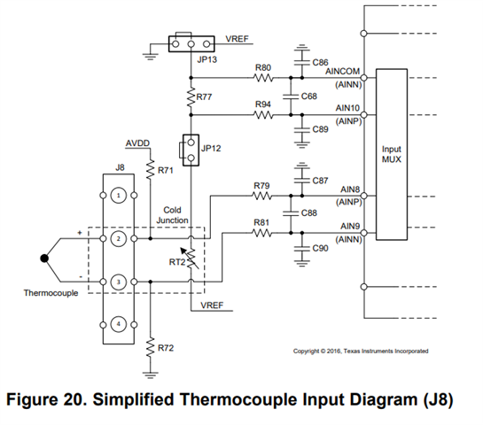
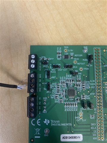
I have been testing the Eval board with different configurations of temperature devices and temperature ranges. When looking into temperatures below 0C the eval board seems to only be able to go down to 0C. Is this because AVSS is 0 and AVDD is 5V? and since the voltage of the thermocouple would be negative it caps off? The case I currently have is a K-Type Thermocouple inside a known -6C measuring point, and a cold junction of 25C at J8. I see the equation V-Hot = V-Measured + V-Cold for thermocouples and knowing V-Cold converted to Temperature is equal to 25C (from RT2) and V-Hot converted to temperature is equal to -6C wouldn't our expected V-Measured be roughly -25C when converted to temperature? Instead of the 0C or very close to 0C being seen measured in the software? Or does this equation for thermocouples change for negative temperatures or when T-Hot < T-Cold?

If this is a limitation that the eval board has because of AVSS being 0, is there a way to change the AVSS and AVDD to encompass negative voltages as well (like inputting an external power supply)? 

Best,
Martin

  • Hello Martin,

    When using a thermocouple with the ADS124S08EVM, you need to bias the thermocouple to mid-scale (2.5V) when AVSS=0V and AVDD=5V.  You can do this by installing pull-up/pull-down resistors on the board (by default, these resistors R71 and R72 are not installed).

    Also, since you are new to using thermocouples, I suggest looking at the below application note:

    A Basic Guide to Thermocouple Measurements (Rev. A)

    Refer to section 1.4.2 in the application note that discusses thermocouple biasing.

    Regards,
    Keith Nicholas
    Precision ADC Applications

  • Hey Keith,

    Sorry for not specifying in my original post, but I do have this configuration already set up. I have the 10M ohm listed in the BOM for both R71 and R72. I also have jumpers JP12 connected, JP13 going from gnd and pin 2. JP11 is not connected so the negative probe of the thermocouple is not shorted to ground. Is there any configurations I might be missing or mistaken on? Maybe something with software settings? I am using 2.5 as my Vref and I use the thermocouple measurement at J8 script to determine my settings. I also use the RT2 preset script to read the CJC data needed.

    It is good to know that the Eval Board can work with a thermocouple that reads negative temperature values. Maybe a setting is just set incorrectly which is causing the issue of the measurement capping at 0C.

    Best,
    Martin

  • Hi Martin Ruvalcaba,

    Can you send us a picture of how you have your board configured? Please include photos of the board and all of its jumpers, as well as how you have your sensors connected and biased to the EVM?

    -Bryan

  • Hey Bryan,

    Here are the pictures to show the configuration of all JP connections. My K-Type Thermocouple is attached to J8, where the positive probe is in A8 (pin 2) and the negative probe is in A9 (pin 3). I have a 10Mohm resister on R71 and another 10Mohm resister on R72 (as recommended in the BOM).

    Listed are the Jumper connections:

    JP 11 - Pin 1 and 2
    JP 8 - Pin 1 and 2
    JP 12 - Enabled (pin 1 and 2)
    JP 13 - Pin 1 and 2
    JP 14 - Pin 2 and 3
    JP 9 - Pin 2 and 3
    JP 5 - Enabled (pin 1 and 2)
    JP 6 - Enabled (pin 1 and 2)
    JP 7 - Enabled (pin 1 and 2)


    Best,
    Martin

  • Hi Martin Ruvalcaba,

    Can you measure the differential input voltage at the ADC pins and then provide the GUI results for that same input? You can measure at cap C88, which is the differential capacitor across the AIN8-AIN9 input pair

    Please also provide the regmap settings from the GUI, you can just take a screenshot of the home page so we can review

    Do this for both a positive differential voltage and a negative differential voltage since we understand that a positive voltage should work fine and there is an issue with the negative voltage. You can also measure the absolute voltage on each pin e.g. AIN8 to ground, to make sure these are all positive absolute voltages within the ADC input range (basically 0V to 5V)

    -Bryan