Tool/software:
I have connected the DAC80508 EVB to a STM32U5 Nucleo testboard. The DAC chip-select (CS) shall be driven from the microcontroller via DMA and a timer (PWM).
I'm sending 4 samples, each a 32bit word. The DAC is by default configured in asynchronous mode.
When updating the DAC from the code via codebase-driven CS, the output of the DAC is updated immediately after the CS goes high.
When driving the CS via a PWM timer, and using DMA for shifting the samples out, on the scope everything looks the same, all timings are far beyond the dataspec limits. However, the DAC does not update the output for the first 3 samples, only after the 4th it's updating the output. It's always the last, even when sending 100 samples.
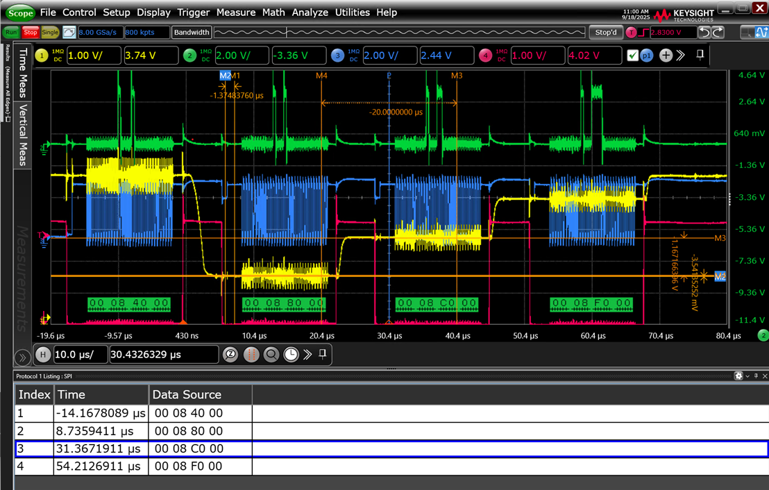
Pic1: code-driven CS, working correctly, CS=red, CLK=blue, DATA=green, DACout=yellow
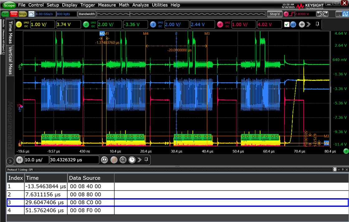
Pic2: timer driven CS, DMA-driven samples, DAC output not working, , CS=red, CLK=blue, DATA=green, DACout=yellow
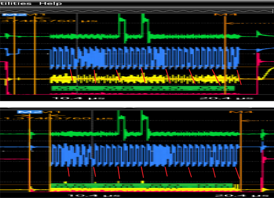
My suspicion is that the DAC is not updating the output as long the ST is actively holding the CLK pin. As you can see in the 2nd picture, the blue CLK is held by the microcontroller, only after the last sample is sent out via DMA it seems to release the CLK (little upward tick), and exactly after this the DAC is updating its output.
When the CS is driven by the code and every sample is sent out separately, the CLK always shows the little upward tick (picture 1), which seems to be the trigger for the DAC to update its output..
I'm looking for an explanation for this behavior, since the DAC datasheet is not giving details in this regard.