ADS1263: ADS1263

Part Number: ADS1263

Tool/software:

Hello,

I am using the ADS1263 with a Teensy 4.1 microcontroller in differential mode.

My application requires me to switch between three different channels (AIN0, AIN1, AIN2) to acquire a single sample from each channel sequentially. My current configuration is:

  • Data Rate: 7200 SPS

  • Filter: SINC4

According to Table 9-13 of the datasheet, the first conversion latency for this configuration is 0.980 ms. To account for this, I have implemented a short delay after each channel switch. However, I am encountering an issue where only the first channel (AIN0) provides a correct reading. The subsequent channels (AIN1 and AIN2) appear to contain residual data or "garbage values" from the previous channel, suggesting that the digital filter is not fully settling before the next conversion is read.

I have already tried using a delayMicroseconds() call to ensure the required settling time, but the issue persists.

Could you please advise on the recommended method for high-speed, sequential channel switching to ensure data integrity for all channels? Is there a more robust approach than using a simple delay?

Thank you for your assistance.

Sincerely,

Sania


#include <SPI.h>
#include "ADS1263.h"
#include <math.h>

const uint32_t SerialUSBSpeed = 19200;

const uint8_t CSPin = 7, DrPin = 6, StartPin = 5;

volatile double v1, v2, v3 = 0.0;
double cf = 0.0;

ADS1263 ADC(CSPin, DrPin);

void setup() {
  Serial.begin(SerialUSBSpeed);
  SPI.begin();
  ADC.Begin(false);
  ADC.SetADC1Gain(ADS1263::ADC1GainValue::V1V);
  ADC.SetIntRefActive(true);
 
  // Set the data rate to 7200 SPS
  ADC.SetADC1DataRate(ADS1263::ADC1DataRateValue::SPS7200);

  // Set the filter to SINC4
  ADC.SetFilter(ADS1263::FilterValue::SINC4);
 
  delay(50);
  ADC.StartADC1();
 
  double GainAmplitude = (double)(1 << static_cast<uint8_t>(ADC.ADC1GainSetting));
  cf = ADC.ReferenceVoltage / GainAmplitude / 2147483647.0;
}

void loop() {
  // Read channel 0
  ADC.SetDiffChannal(0);
  delayMicroseconds(980); // Wait for the 0.980ms latency
  ADC.WaitDRDY();
  v1 = cf * ADC.Read_ADC1_Data();

  // Read channel 1
  ADC.SetDiffChannal(1);
  delayMicroseconds(980);
  ADC.WaitDRDY();
  v2 = cf * ADC.Read_ADC1_Data();

  // Read channel 2
  ADC.SetDiffChannal(2);
  delayMicroseconds(980);
  ADC.WaitDRDY();
  v3 = cf * ADC.Read_ADC1_Data();

  Serial.printf("%f %f %f \n", v1, v2, v3);
}
  • Hi Sania Rahman,

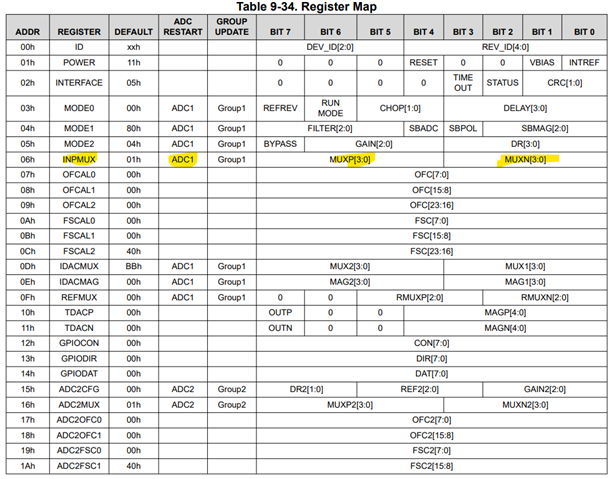
    You do not need to account for the first conversion latency when switching the mutiplexer, you can see from the register map that the ADC will automatically restart the conversion process when you write to the INPMUX register (assuming the device is in continuous conversion mode). I have highlighted this in the image below

    So you just need to wait until DRDY drops low each time to start reading back data. Your sequence would look something like this:

    • Perform initialization
    • Start conversions
    • Wait for DRDY to drop low
    • Clock out data
    • Change INPMUX settings
    • Wait for DRDY to drop low
    • Clock out data
    • Change INPMUX settings
    • etc.

    If this does not work then you will need to provide logic analyzer captures showing the communication between the ADC and controller. Please include SCLK, DIN, DOUT, CS, and DRDY.

    -Bryan