This thread has been locked.

If you have a related question, please click the "Ask a related question" button in the top right corner. The newly created question will be automatically linked to this question.

DAC121C081: The techonolgy support for DAC121C081

Part Number: DAC121C081


Tool/software:

Hi,

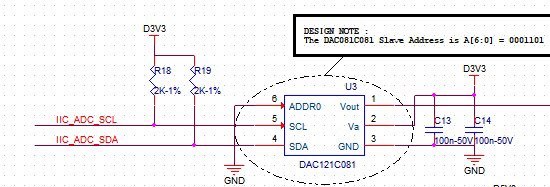
We use the DAC121C081 in our project, and now, please advise Is there anything important about the High Speed (3.4-MHz) Modes circuit on this chip? 

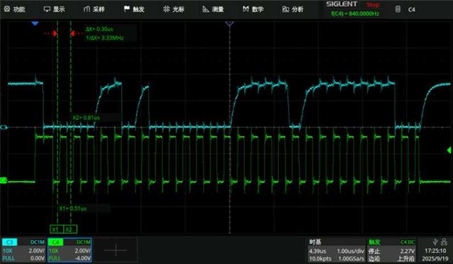
We are currently facing a problem where adjusting the I2C input under special circumstances may result in the chip having no output after refreshing tens of thousands of times.

The below is our schematic diagram?

  • Hi Zhang,

    Can you confirm your timing of I2C is within our specification at 3.4MHz?

    Are you able to capture the digital inputs during a failure event on an oscilloscope?

    Thanks

    Paul

  • Zhang,

    In addition to Paul;s comments, you should check that the device has entered into High speed mode. For I2C High speed (Hs) mode, you need to first send a controller code to make sure the device is ready for Hs-mode. After that you should be able to receive and transmit in Hs-mode.

    Can you show an oscilloscope plot of the transmission and reception in Hs-mode? Once the device receives and sends data back in Hs-mode, you need to make sure there is no Stop condition sent by the microcontroller. The Stop condition will take the device out of Hs-mode and the device goes back to Fast mode. With Hs-mode being sent by the microcontroller, you might lose communications.

    Ideally, you could use a logic analyzer to review all communication with the device, but an oscilloscope might work.


    Joseph Wu

  • Hi Joseph,

    Thanks for you kindly support.

    The below is our I2C waveform:

    And we are comparing the pull-up resistors and FPGA driving capabilities of different SDAs.

    Only the version we are currently using with 2K and 12ma driving capabilities will have any problems.

    Can you help me check if there are any analysis directions? thanks.

  • Zhang,

    It looks like the rise time for the SDA lines are a little slow in the plot. In the DAC121C081, the VIH level is 0.7*VDD. In this plot, it looks like the VDD is about 3.3V, which means that the SDA needs to get to 2.31V to make sure the input is seen as a valid high level.

    To make SDA faster, you need a higher current pull-up, which might mean the 2kΩ pull up is too small, and that the 1.1kΩ pull up gives enough current to pull the node up faster. You might be able to keep the 2kΩ resistor, if you can reduce the amount of capacitance on the bus line (although much of bus capacitance is parasitic and comes from the layout of the board).

    We have an application note on I2C at the following link (A Basic Guide to I2C): https://www.ti.com/lit/pdf/sbaa565

    In the app note, there's a brief discussion on the electrical characteristics on page 25. Near the end, there's a brief discussion on the sizing of the pull up resistors starting on page 28.

    Joseph Wu