This thread has been locked.

If you have a related question, please click the "Ask a related question" button in the top right corner. The newly created question will be automatically linked to this question.

ADS124S06: Unable to communicate

Part Number: ADS124S06
Other Parts Discussed in Thread: ADS124S08EVM

Tool/software:

Hello everyone,

I'm working on a custom board that uses the ADS124S06 but I'm unable to communicate.

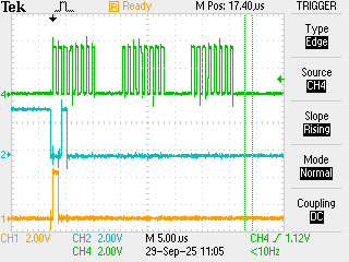
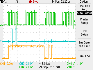
I've checked SPI CS/DIN/SCLK signals and it looks just fine despite that I'm unable to see any data in DOUT.

I guess timigs are ok, spi clock is 1MHz and CS delay is ~1us

I'm using my own driver, wrote following the user manual:

void ADS124S0X_send_read_command(void* spi, uint8_t start_adr, void* dest, uint8_t length)
{
  if(length == 0)
    return;

  uint8_t *p8_dest = (uint8_t*)dest;
  hal_spi_channel_t* hal_spi = (hal_spi_channel_t*)spi;
  hal_spi_result_t result = HAL_SPI_RESULT_OK;

  uint8_t command = CMD_RREG | (start_adr & 0x1F);
  uint8_t len = (length - 1) & 0x1F;

  HAL_SPI_Enable_slave(hal_spi);  

  HAL_SPI_exchange_byte(hal_spi, command, NULL);
  HAL_SPI_exchange_byte(hal_spi, len, NULL);

  while(length-- && result == HAL_SPI_RESULT_OK)
  {
    result = HAL_SPI_exchange_byte(hal_spi, 0, p8_dest);
    p8_dest++;
  }

  HAL_SPI_Disable_slave(hal_spi);
}

void ADS124S0X_send_write_command(void* spi, uint8_t start_adr, void* src, uint8_t length)
{
  if(length == 0)
    return;

  uint8_t *p8_src = (uint8_t*)src;
  hal_spi_channel_t* hal_spi = (hal_spi_channel_t*)spi;
  hal_spi_result_t result = HAL_SPI_RESULT_OK;

  uint8_t command = CMD_WREG | (start_adr & 0x1F);
  uint8_t len = (length - 1) & 0x1F;

  HAL_SPI_Enable_slave(hal_spi);  

  HAL_SPI_exchange_byte(hal_spi, command, NULL);
  HAL_SPI_exchange_byte(hal_spi, len, NULL);

  while(length-- && result == HAL_SPI_RESULT_OK)
  {
    result = HAL_SPI_exchange_byte(hal_spi, *p8_src, p8_src);
    p8_src++;
  }

  HAL_SPI_Disable_slave(hal_spi);
}

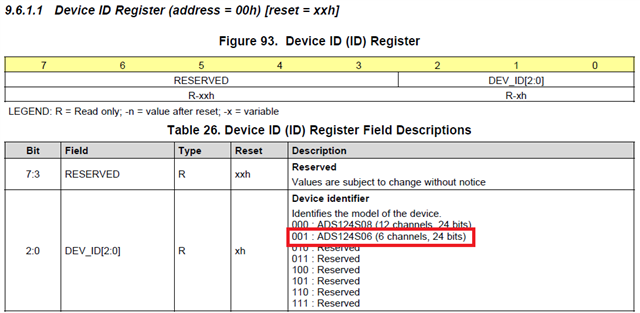
#define ID_ADS124S06 (0x01)
uint8_t AD124S0X_Init(void* hal_spi)
{
  uint8_t ads124s0x_id = 0;
  ADS124S0X_send_read_command(hal_spi, 0x00, &ads124s0x_id, 1);

  if(ads124s0x_id != ID_ADS124S06)
    return 1;
    
  return 0;
}

  • Hi Lorenzo Mariotti,

    Are you getting any data on DOUT? For example, if you read a register, are you getting the correct value?

    Can you provide logic analyzer captures showing the data communication? Please include CS, SCLK, DIN, DOUT, and DRDY so we can review

    -Bryan

  • Hi Bryan,

    DOUT stay fixed low, I’ve tried to read single register but nothing on DOUT line. 
    I’m sure that SPI is working fine because in the same bus there are 3 DACs that works just fine.

    I’ll try to share scope screen asap, but I’ve only 4 probes Sweat smile, is the DRDY really necessary?

    Thanks for your support

  • Hi Lorenzo Mariotti,

    This will be much easier with a logic analyzer, but a scope will also work. And yes for now you can omit DRDY, especially if you are not getting any response from the ADC i.e. this doesn't sound like an output data issue, it sounds like a larger issue with the ADC

    If you power up the ADC and pull the START pin high, you should be able to probe the dedicated DRDY pin and see this pin toggling at the default data rate (20SPS, or 50ms). If you do not see this behavior then you have a power supply, clocking, or grounding issue. 

    -Bryan

  • Hi Bryan,

    I can confirm that with START pin hight the DRDY pin toggle at 50ms.

    Still unable to read registers.

    Here I'm trying to read the Device ID register (00h) expecting to read the value 001

    1st picture shows the CS (yellow) SCLK (green) and SDI (blue) lines

    2nd picture shows the SDO (yellow) SCLK (green) and SDI (blue) lines

    There is probably a stupid problem, but I can't find it.

    EDIT:
    I've tried this sequence:

    - Power up
    - START/SYNC = 1
    - Delay 10ms
    - Send RESET command
    - Delay 10ms
    - Send the RDATA (12h) command in loop every 1s, the ADS124S06 response is a fix value FF8A00h 


  • Hi Lorenzo Mariotti,

    Can you try reading some other, nonzero default registers instead of the ID register? Do this immediately after powerup and let us know the result. I highlighted a few below

    Please also probe the DRDY pin when you are trying to read conversion data (this is not necessary when you are trying to read back register data). You should confirm that this pin is continuing to toggle at approximately the default data rate when you are trying to read conversion data. If the DRDY pin is not toggling, sending repeated RDATA commands will just give you the same data over and over.

    -Bryan

  • Hi Bryan,

    here I've tried to read the DATARATE reg (04h), SCLK green, MOSI (blue), MISO (yellow), CS (purple)

    I'm sending command = 24h (20h | 04h) and len = 0 (1 - 1 = 0) followed by a NOP byte to readback the value.

    Please note: START pin is LOW and this command is sent after a RESET command and a 10ms delay.

    About conversion data, I've replaced the CS probe with the DRDY output from ADC, I can confirm that the DRDY pin goes up at 50ms

  • Hi Lorenzo Mariotti,

    I am not really sure what is going on here. Is it possible there is contention on the SPI bus due to the other components? It is odd to me that the DOUT pin always seems to be high. You mentioned there were 3x DACs on the bus, correct? Can you try removing these just to make sure they are not causing an issue? Hopefully there are resistors or some other component that can be removed to disconnect the SPI bus from the DACs without having to remove the DACs themselves.

    You also show different grounds for your analog (AVSS) and digital (DGND). Are these connected anywhere on your board? We normally recommend using a single, solid ground plane for both analog and digital, but it is possible to use separate ground planes if you are careful

    If possible, I'd also recommend getting an ADS124S08EVM. This provides you a known working solution that you can 1) use as a controller for your board so you can verify the hardware is working correctly, and 2) use as a peripheral for your firmware to make sure that is working correctly as well. 

    One other thing: you said the data was FF8A00h in a previous post, but I don't think that is correct. Your controller should be capturing data on DOUT on the falling edge of SCLK, not the rising edge. From the images you provided it looks like DOUT drops low as soon as SCLK rises high, which should be read as a 0, not a 1. This is not the source of the problem you are having, but it is one issue that needs to be resolved

    Finally, the scope pictures you are sending cannot be made larger for some reason. You will notice that if you hover over the images I sent you, or even your schematic image, then the cursor turns into a magnifying glass and you can make the image larger. This does not happen for the scope images however, so they are very small and difficult to read. Can you try to remedy this if you post new scope shots? You can confirm after you post by hovering over the image as I described. Then, if that didn't work, try editing the post with new images

    -Bryan

  • Lorenzo,


    I haven't read through the entire thread, but I did notice one thing. It looks like you have the SPI set up in the wrong mode. For the ADS124S06, the DIN should be clocked in on the falling edge of SCLK. In that case, the data changes on the rising edge of SCLK and must be held stable at the falling edge of SCLK. Because of this, the device might not be receiving the correct data.

    Check the CPHA for the SPI mode, and I think the device may respond correctly.


    Joseph Wu

  • Hi Byran and Joseph,

    thank you very much for your support! 

    The problem was in fact the CPHA setting! 

    I had ruled out the possibility that it could be an SPI setup issue, as I have other devices working on the same bus.

    But once the CPHA was set up correctly, everything worked fine!