DAC80502-01EVM: DAC80502-01EVM

Part Number: DAC80502-01EVM
Other Parts Discussed in Thread: DAC80502

Tool/software:

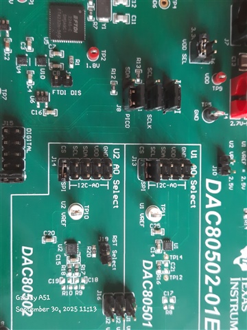
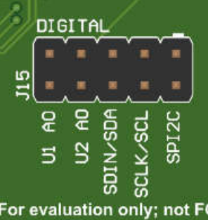
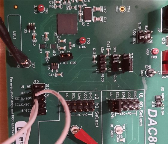
i am trying to use the DAC80502-01 dev board to generate Vout from either the 02 or the 01 but no luck. I can't get the FTDI chi[t to drive the  DAC's. I installed the driver. I open the DAC805xxEVM and i see the default values for registers and i have the software indicating its connected to the chip. But when i push Read All button everything comes back as 0, why?

I mean when i read the registers  shouldn't i see the default values when i read the registers i get nothing back but zeros.

The only thing i see that makes sense is when i go to the High Level Config window for DAC80502 and set broadcast to any hex value and then go to Low Level Config window i see the hex value i put in when i  read back Broadcast_2.

So i see no Vout.

I am interested in DAC80502 and want to make it work with PIC18f87J90 but sending SPI with mu own mentioned processor generates no output either and  i have scoped out the signal to DAC chip level and see SPI signals making it to the chip but nothing happens at  the output. I used the same sequence as the one in the DAC80502 data sheet and see no output. 

If i can't make the FTDI work then the processor doesn't have a chance. 

Need to know how to make FTDI work.

Thanks,

Shervin

  • Hi Shervin,

    Are you using SPI or I2C? These devices do not have an SDO pin, so there's no readback available in SPI mode. Due to this, you will see all 0s in the register map. You can only read the register data in I2C mode.

    What jumpers do you have populated on the board? The following image shows the proper configuration for SPI. Use J6 to apply voltage to the device. Also measure the 5V and 3.3V voltage to ensure the voltages are correct. Finally, make sure you're unchecking the "Demo Mode" box, if it's checked no commands will go to the FTDI. 

    Thanks,
    Erin

  • Hi Erin,

    Ok understood about reading back register values using SPI.

     Unfortunatly your system is not aloowing me to upload more than a single image onto thisa thread so i am going to respond with more pics  so you can see what's going on. The pic below is of the jumpers setting on the board which to me seems to match your usre guid but you can double check. . 

    For DAC80502 i have  set the values to FFFF and pressed enter which means that it should have written thos values to the DAC register output, correct? But when i put my scope probe on J16 i see no voltage coming out. Is there something i am not doing?

  • more pics for you to consider.

  • unfortunately your system is not letting me upload the pic but i have the scope probe connected to J16 and DACB output is zero after i write the  FFFF above.

  • okay it finally let me post the Vout pic from unit.

  • Hi Shervin,

    I appreciate the pictures! It looks like you have your jumpers set up correctly and that you're probing the correct output. Could you please check the following voltages:
    -VDD, ensure it's 3.3V
    -U2_VREF, ensure it's 2.5V. 

    If these voltages are not present it could indicate an issue.

    Thanks,
    Erin

  • Hi Erin,

    Looking at voltage on TP9 i see 3.3V, looking at voltage on TP10 i see 2.49V. So voltages look correct to me. Does this board need to be populated with load resistance? i mean I would expect not but i wanted to ask. Would that help? What else you think could be the culprit? As can be seen in the pic i posted it says its connected to the board. So the computer and FTDI  see each other well so the issue is to me on the board itself. 

    Now prior to trying to use the FTDI chip to set register values for the DAC i was using external processor and saw nothing as well so do you think that may have damaged the unit?

    I don't have  a lot of time to trouble shoot this product. I need to be able to make it work with my own processor as this chip will be used on a in house board to drive comparators. But at this point i just want to see it work period.

    Thanks,

    Shervin

  • Hi Shervin,

    Let's confirm that the FTDI is communicating with the device. Try turning off the internal reference through the GUI. 

    Also, I just remembered an annoying trick with this FTDI. Do you have another USB port? Try using different ports and seeing if any work. On my laptop, for example, I have one USB port that will not communicate with the FTDI and one that does. There's a chance you're experiencing that same issue. (note you must check and uncheck demo mode every time you plug in the USB)

    Thanks,
    Erin

  • Hi Erin,
    You were correct about the USB. I switched ports and sure enough everything is working and I can see the Vout coming out correctly as I set its registers. All other functions work as well.
    Now that we are past this hurdle the real work is to get it to be driven by a PIC18F87J90 dev board. I am going to set it up shortly and test and see if the processor can replicate the success of the FTDI chip. Do you have any tricks or gotcha's you need me to be aware of? I am running everything on 3.3V. I am going to write a repeating sequence in C such that I am turning on/off the internal ref. Thus if it works i should see Vref on TP10 toggle between 0V and  2.5V.
    Which TP can i monitor for FTDI SPI signals?
    Thanks,
    Shervin
  • Hi Shervin,

    Great that it works now! You can use J15 to monitor the FTDI SPI outputs. "U2_A0" would be the CS pin for the DAC80502.


    Thanks,
    Erin

  • Hi Erin,

    I tried to drive the DAC80502 with my PIC18f87j90 pICDEM board but i did not see the result i was looking for. I wanted to run the same test where i would command the CONFIG register to turn off the internal ref so i could see the voltage on TP10 drop from 2.5V to zero. I sent a SPI write command which wrote out 0x03,0x10,0x00. This should have turned the ref off by setting the 8 bit of the config to 1. The voltage measurement atTP10 stayed at 2.5V so i am not communicating with DAC80502. Before i go deeper into comparing SPI signals between my processor and the FTDI spi, please look at my board jumper positions and see if they are set correctly for external comms.

    Specifically in the EVM user guide its unclear in instructions if J11 needs to be in or off the board for external comms.? I am assuming it should be removed for external comms?

    Please look at the image below and see if the other jumpers are set correctly for external comms. i have kept J13 in because i am using dAC80502. The black clip wire is the ground from processor board to EVM so they have a common reference for digital comms.


  • Hi Shervin,

    For external communications, you should leave J8, J11, and J14 open, as you've done. The command you're writing looks correct. Make sure you're latching data on the falling edge of SCLK, this is the most common issue I see when it comes to SPI with our devices.

    Thanks,
    Erin