ADS1220: Request for Verification of ADS1220 SPI Communication Waveform

Part Number: ADS1220

Tool/software:

I am currently debugging the communication interface of the ADS1220 ADC chip. During the debugging process, I performed the following operations:

  1. Sent a reset command to initialize the device

  2. Wrote to register 0x00 (configuration register 0) with specific data

  3. Attempted to read back from register 0x00 to verify the write operation

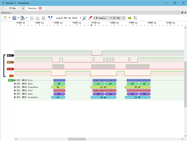
To analyze the communication, I used a logic analyzer to capture the complete SPI waveform during these transactions.

  • Hi Anveil,

    Your commands are correct, you can try to use 0x00 as dummy code/clocks instead of 0xFF.

    ADS1220 only supports SPI mode 1 (CPOL = 0, CPHA = 1) , I would suggest you to check the SPI configuration on your microcontroller and your logic analyzer.

    After the RESET command is sent to the ADC, you have to wait for at least (50 µs + 32 · t(CLK)) before sending any other command, so I would suggest you to check the delay in your timing as well.

    BR,

    Dale

  • Hi Dale,

    Thanks for your reply. I'm trying to communicate with the ADS1220. Can I simply connect DVDD and DGND to supply power?

    Alternatively, can I connect AVSS to DGND and AVDD to DVDD to test the communication?

  • I used a minimum system board to test the communication, and reading the registers works. I'm trying to find the hardware problem; maybe it's a soldering issue.

  • Hi Anveil,

    You can short AVSS to DGND for unipolar power supply and also short AVDD to DVDD if your SPI bus of your microcontroller has the same logic level, for example, 5V.

    BR,

    Dale