


Part Number: ADS124S08
Other Parts Discussed in Thread: ISO7761
Tool/software:
Dear TI Support Team,
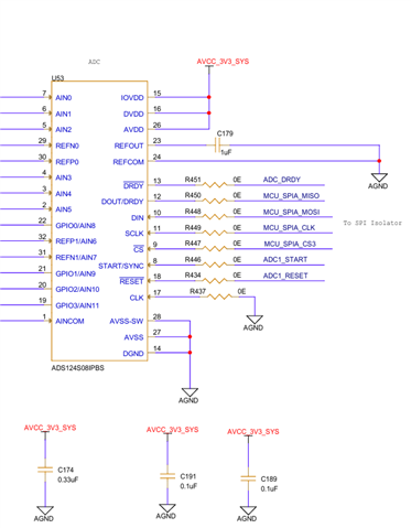
We are facing an issue with the ADS124S08 when used as an SPI slave device in our system.
Our SPI bus configuration includes four slave devices:
-
Two ADS124S08 (RTD ADCs)
-
Two AD7490 ADCs
All four devices share the same SPI bus (MOSI, MISO, and SCLK), with individual chip-select (CS) lines controlled by the MCU.
Initially, we used ISO7761DBQR digital isolators between the MCU and the slave devices for galvanic isolation. the salves are connected in the analog isolated section ( Isolator secondary side ). During SPI communication, we observed that the MISO (DOUT/DRDY) line from the ADS124S08 shows a slow rising edge, while all other SPI signals (SCLK, MOSI, CS) appear normal on the oscilloscope. The falling edge of MISO is sharp, but the rising edge is very slow, resulting in invalid data being received by the MCU.
To verify whether the isolators were causing this behavior, we removed the ISO7761 devices and directly shorted the SPI traces between the MCU and the slave devices using jumpers. However, the same slow rising edge behavior remains, even without the isolators in the circuit.
We have confirmed that:
-
Each SPI device has its own dedicated CS line, and only one CS is active at a time.
-
CS timing follows the ADS124S08 datasheet recommendations.
-
MOSI, SCLK, and CS signals are clean and stable.
-
The issue appears only on the MISO line of the ADS124S08. (when I'm trying to communicate with the AD7490 same SPI lines looks clean and the data flow is happening with out issue.
An oscilloscope waveform of the MISO signal is attached for your reference.
The rising edge shows an exponential transition with an approximate rise time of 43 µs.
Please help us understand what could be causing this behavior and the possible root cause within the ADS124S08 or its configuration.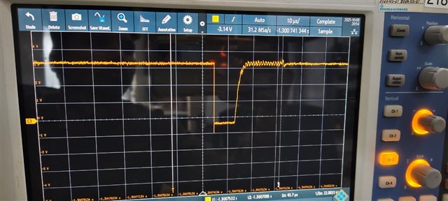
Thank you for your support.
Best regards,
Manikandan V

