ADS1298: SPI not reading

Part Number: ADS1298


Tool/software:

I keep getting 0x00 for all register reads the ads1298 is connected to the STM32WB55 board, with the DRDY pin remaining high everytime.. it never goes down, but I do not get any errors on SPI transactions either.
SPI configs:
Data size 8 bits
MSB first
Prescaler - 128 , baudrate - 250kb/s
CPOL - low
CPHA - 1 edge

The code:
ads1298.c:

#include "ads1298.h"

#include "main.h" // For hspi1

#include <stdio.h>


// External SPI handle

extern SPI_HandleTypeDef hspi1;


// Send SPI command

static void ADS1298_SendCommand(uint8_t cmd)

{

 uint8_t rx[1] = {0};

 ADS1298_CS_LOW();

 HAL_Delay(1); // Ensure 2 µs minimum (t_SDECODE)

 HAL_StatusTypeDef status = HAL_SPI_TransmitReceive(&hspi1, &cmd, rx, 1, 1000);

 ADS1298_CS_HIGH();

 HAL_Delay(1); // Wait 4 t_CLK (~2 µs) before next command

 printf("Command 0x%02X sent, RX: 0x%02X, Status: %d, Error: %ld\r\n", cmd, rx[0], status, HAL_SPI_GetError(&hspi1));

}


// Write register

void ADS1298_WriteRegister(uint8_t reg, uint8_t val)

{

 ADS1298_CS_LOW();

 HAL_Delay(1); // Ensure 2 µs minimum

 HAL_SPI_Transmit(&hspi1, (uint8_t[]){ADS_WREG | reg, 0x00, val}, 3, 1000); // Single register write

 ADS1298_CS_HIGH();

 HAL_Delay(1); // Wait 4 t_CLK (~2 µs)

 printf("Wrote Reg 0x%02X with 0x%02X\r\n", reg, val);

}


// Read register

uint8_t ADS1298_ReadRegister(uint8_t reg)

{

 uint8_t rx[3] = {0};

 ADS1298_CS_LOW();

 HAL_Delay(1); // Ensure 2 µs minimum

 HAL_SPI_Transmit(&hspi1, (uint8_t[]){ADS_RREG | reg, 0x00, 0xFF}, 3, 1000); // Read one register

 ADS1298_CS_HIGH();

 HAL_Delay(1); // Wait 4 t_CLK (~2 µs)

 printf("Read Reg 0x%02X: RX: 0x%02X 0x%02X 0x%02X, Value: 0x%02X\r\n",

 reg, rx[0], rx[1], rx[2], rx[2]);

 return rx[2];

}


// In ADS1298_Init

void ADS1298_Init(void)

{

 printf("ADS1298 Initialization Started\r\n");


 HAL_GPIO_WritePin(GPIOB, GPIO_PIN_7, GPIO_PIN_SET); // PWDN HIGH

 HAL_GPIO_WritePin(GPIOB, GPIO_PIN_6, GPIO_PIN_RESET); // RESET LOW

 HAL_Delay(1); // 1 µs

 HAL_GPIO_WritePin(GPIOB, GPIO_PIN_6, GPIO_PIN_SET); // RESET HIGH

 printf("RESET Applied\r\n");


 HAL_Delay(100); // Reduced from 1000 ms for testing

 printf("Post-RESET Delay Complete\r\n");


 ADS1298_SendCommand(ADS_RESET); // Software reset

 HAL_Delay(1); // 1 ms

 printf("SPI RESET Sent\r\n");


 ADS1298_SendCommand(ADS_SDATAC); // Stop continuous mode

 HAL_Delay(1); // 1 ms

 printf("SDATAC Sent\r\n");


 uint8_t id = ADS1298_ReadRegister(ADS_REG_ID);

 uint8_t config2 = ADS1298_ReadRegister(ADS_REG_CONFIG2);

 int channels = 0;

 switch (id & 0x1F) {

 case 0x10: channels = 4; break;

 case 0x11: channels = 6; break;

 case 0x12: channels = 8; break;

 case 0x1E: channels = 8; break;

 default: channels = 0;

 }

 printf("Device ID: 0x%02X, Channels: %d, CONFIG2: 0x%02X\r\n", id, channels, config2);


 ADS1298_SendCommand(ADS_START);

 HAL_Delay(1); // 1 ms

 printf("START Sent\r\n");


 if (ADS1298_DRDY() == GPIO_PIN_SET) {

 printf("DRDY is HIGH (device may not be ready)\r\n");

 } else {

 printf("DRDY is LOW (device ready)\r\n");

 }


 printf("ADS1298 Initialization Complete\r\n");

}


ads1298.h:

#ifndef APPLICATION_USER_STM32_WPAN_APP_ADS1298_H_

#define APPLICATION_USER_STM32_WPAN_APP_ADS1298_H_


#include "stm32wbxx_hal.h"

#include <stdio.h>


// ADS1298 SPI commands

#define ADS_WAKEUP 0x02

#define ADS_STANDBY 0x04

#define ADS_RESET 0x06

#define ADS_START 0x08

#define ADS_STOP 0x0A

#define ADS_RDATAC 0x10

#define ADS_SDATAC 0x11

#define ADS_RDATA 0x12

#define ADS_RREG 0x20

#define ADS_WREG 0x40


// ADS1298 Register Addresses (only relevant ones for now)

#define ADS_REG_ID 0x00

#define ADS_REG_CONFIG2 0x02


// Pin definitions

#define ADS1298_CS_LOW() HAL_GPIO_WritePin(GPIOA, GPIO_PIN_4, GPIO_PIN_RESET) // PA4

#define ADS1298_CS_HIGH() HAL_GPIO_WritePin(GPIOA, GPIO_PIN_4, GPIO_PIN_SET)

#define ADS1298_START_HIGH() HAL_GPIO_WritePin(GPIOE, GPIO_PIN_4, GPIO_PIN_SET) // PE4

#define ADS1298_START_LOW() HAL_GPIO_WritePin(GPIOE, GPIO_PIN_4, GPIO_PIN_RESET)

#define ADS1298_DRDY() HAL_GPIO_ReadPin(GPIOA, GPIO_PIN_15) // PA15


// Functions

void ADS1298_Init(void);

void StartEcgPrintTask(void *argument);

uint8_t ADS1298_ReadRegister(uint8_t reg);

void ADS1298_WriteRegister(uint8_t reg, uint8_t val);


#endif /* APPLICATION_USER_STM32_WPAN_APP_ADS1298_H_ */

Where did I go wrong?


  • Hi Naveen,

    Thank you for your post.

    Are you following the recommended initialization sequence in section 10.1? Power supply ramping and power-on reset is also described in Section 11, which is recommended to ensure the ADS1298 is initialized properly. 

    In order to read/write registers, you will first need to send the SDATAC command.

    For multi-byte transactions, it is necessary to keep /CS low throughout the SPI frame.

    Regards,

    Ryan

  • void ADS1298_Init(void)
    {
        printf("ADS1298 Initialization Started\r\n");
    
        // Power-On Reset Sequence
        ADS1298_PWDN_LOW();    // PWDN low during power-up
        HAL_Delay(100);        // Allow power stabilization
        ADS1298_PWDN_HIGH();   // PWDN high
        HAL_Delay(100);        // Transition time
    
        ADS1298_RESET_LOW();   // RESET low
        HAL_Delay(10);         // 10 ms > 0.976 µs
        ADS1298_RESET_HIGH();  // RESET high
        HAL_Delay(1000);       // ≥1s for oscillator stabilization
    
        printf("Power-On and RESET Sequence Complete\r\n");
    
        // Verify SPI
        if (hspi1.State != HAL_SPI_STATE_READY) {
            printf("SPI not ready, State: %d\r\n", hspi1.State);
            return;
        }
        printf("SPI initialized correctly\r\n");
    
        // Check control pin states
        printf("PWDN: %d, RESET: %d, START: %d, DRDY: %d\n",
               HAL_GPIO_ReadPin(GPIOB, GPIO_PIN_7),
               HAL_GPIO_ReadPin(GPIOB, GPIO_PIN_6),
               HAL_GPIO_ReadPin(GPIOE, GPIO_PIN_4),
               ADS1298_DRDY());
    
        // Send SDATAC to stop read-continuous mode
        uint8_t sdatac_response = ADS1298_SendCommand(ADS1298_CMD_SDATAC);
        printf("SDATAC Response: 0x%02X\r\n", sdatac_response);
        HAL_Delay(10);
    
        // Configure CONFIG1 (example: 250 SPS)
        uint8_t config1[] = {ADS1298_CMD_WREG | ADS1298_REG_CONFIG1, 0x00, 0x00}; // 250 SPS
        ADS1298_CS_LOW();
        HAL_SPI_Transmit(&hspi1, config1, 3, 1000);
        ADS1298_CS_HIGH();
        HAL_Delay(10);
    
        // Set START pin and send START command
        if (HAL_GPIO_ReadPin(GPIOE, GPIO_PIN_4) != GPIO_PIN_SET) {
            ADS1298_START_HIGH();
            printf("START forced HIGH\r\n");
        }
        uint8_t start_response = ADS1298_SendCommand(ADS1298_CMD_START);
        printf("START Response: 0x%02X, DRDY: %d\n", start_response, ADS1298_DRDY());
        HAL_Delay(100);
    
        // Verify initialization
        ADS1298_ReadID();
        ADS1298_ReadConfig1();
        ADS1298_ReadConfig2();
        printf("ADS1298 Initialization Complete\r\n");
    }


    This is my initialization code.. hope this follows the sequence.. still the spi reads 0x00.. should I check the power supply to ads1298??

  • Hi Naveen - are you able to read any of the device registers? Try reading the ID register or any address with a non-zero default value.

    Regards,

    Ryan

  •   No when I try to read register 00h which is for reading the ID.. I get 0x00 as response

  • Hi Naveen,

    Can you also try following the suggested debug steps outlined in this E2E FAQ: 

    (+) [FAQ] ADS129x: How do I verify that my ADS129x device is still functional? - Data converters forum - Data converters - TI E2E support forums

    How many boards/devices are showing this behavior?

    Regards,

    Ryan

  • Sure I'll check it and let you know

  •  My bad the clock phase should be 2 edge.. I could read the device ID now.. can you give me reference for reading the data from ECG simulator?

  • Hello Naveen,

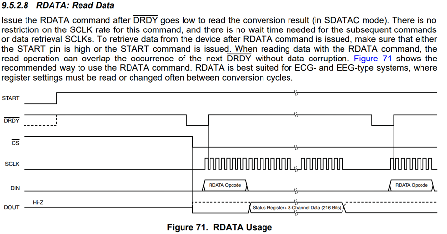
    We do not have specific references to provide for reading the data from the ECG simulator. However, "Section 9.5: Programming" of the ADS1298 data sheet provides detailed instructions for interfacing with the ADS1298. Specifically, the "RDATA" command explains how to read ECG data from the device.

    Capture of Section 9.5.2.8 RDATA: Read Data in the ADS1293 data sheet

    Regards,

    Payton

  • Thanks I'll look into it

  • Hi Naveen - just to clarify, RDATA command would have to be sent at the start of every SPI frame, followed by enough 0x00 bytes to read all the channel data. Conversely, you can use the RDATAC mode (default), and data is automatically loaded into the output shift register before each /DRDY falling edge.

    Regards,

    Ryan

  • Hi Ryan, Thanks the read works but I get an very unusual pattern while reading the data.. and no it is not hardware noise.. the above image if from config2 register (internal test signal generation)

  • Hi Naveen, 

    Have you checked the SPI transaction timing with an oscilloscope or logic analyzer? You will have to ensure the entire frame is completed before the next /DRDY interrupt. Else, either the data will be overwritten and corrupted (RDATAC mode) or you will miss the next sample entirely (RDATA mode). 

    Are you using the internal reference voltage? Can you check VREFP and all supplies to ensure there is not a periodic interference on your board?

    Regards,

    Ryan