ADS124S06: ADS124S06 is stuck when RTD is floating.

Part Number: ADS124S06


Tool/software:

Hi support team,

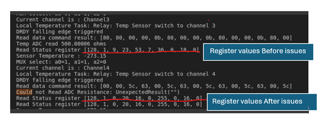
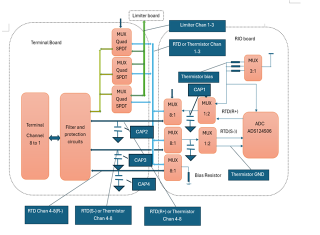
When one of 6 channel-RTDs by using MUX is not installed, ADS124S06 is stuck. After toggling P18(reset), it works. Probably because there is no current through the resistor of reference input, 0VDC of reference voltage cause it.

Could you please let know why it happened? how to solve it? thanks,

  • Hi IronChef Han,

    Can you clarify what you mean by the "ADS124S06 is stuck"? Is it stuck at a certain value? The ADC won't respond? Please be clear and detailed in your response

    Yes, if the RTD is disconnected the IDAC path to ground is broken such that no current flows through the reference resistor. This means your reference voltage is approximately 0V, so any small residual voltage on the input e.g. the ADC offset voltage, will result in a full-scale code (can be positive or negative)

    -Bryan

  • Thanks Bryan, 

    We have installed an RTD on channel 1, while channels 2 through 6 have no RTDs connected. Our firmware is designed to iterate through each channel within one second. However, the iteration often gets stuck at channel 4 due to the Ready signal remaining high. After toggling the Reset signal once at P18, we conducted a 3-hour test during which the issue did not occur.

    - W.Han

  • Hi IronChef Han,

    Is the "ready" signal the DRDY pin from the ADC? Or something else?

    There should be no reason the ADC stops working correctly because the RTDs are disconnected

    Can you provide logic analyzer captures showing this behavior? Hopefully can you capture the data readback from all 6 channels, or at least until the 4th channel gets "stuck". Please include DIN, DOUT, CS, SCLK, and DRDY in the plots so we can review

    -Bryan

  • Hi Bryan, Thanks for your time and support.

    Sorry for the delayed response — we’ve been focusing on a higher-priority project recently. After further investigation, we identified several conditions that can resolve the issue:

    1. When all RTDs are installed, the issue does not occur.

    2. When only one RTD is installed, removing CAP1(10nF) on the R+ path resolves the issue.

    3. When only one RTD is installed, removing CAP2, CAP3, and CAP4(100nF) on the R+, S-, and R- paths respectively also resolves the issue.

    4. When each RTD is selected individually, the issue does not occur.

    We observed that this issue causes the register values to revert to their default settings. Please refer to the attached files for more details.

    Based on our findings, it appears unlikely that the SPI is the root cause. However, the exact cause of the issue remains undetermined. Could you please help us further investigate and identify the root cause?

  • Hi Han, 

    Bryan is out of office right now, let me see if I can help. Since the register values are being reset, it seems like the device is unintentionally being reset. Can you please monitor the /RESET pin when this issue occurs?

    Is the "ready" signal from the DRDY pin? Can you please share logic analyzer shots showing this behavior?

    What do you mean by "When each RTD is selected individually"?

    Are the muxes also switching as a part of this routine?

    Is it possible for you to share a schematic, at least the ADC and the signal path of the 4th RTD?

    Thanks,

    Maggie

  • Thanks Maggie,

    Can you please monitor the /RESET pin when this issue occurs?

    Yes, I did, but did not find the any glitch on RESET signal.

    Is the "ready" signal from the DRDY pin? Can you please share logic analyzer shots showing this behavior?

    Yes, "Ready" signal is from DRDY PIN. The DRDY pin remains in a high state while the issue occurs.

    What do you mean by "When each RTD is selected individually"?

    This indicates that there is no iteration loop for the RTD channels. When testing a single RTD independently, the issue does not occur.

    Are the muxes also switching as a part of this routine?

    yes,

    Is it possible for you to share a schematic, at least the ADC and the signal path of the 4th RTD?

    please find the attachments for RTD circuit.  Removing C50 in circuit resolves the issue. 

    2577.RTD.pdf

    Also I attached a snapshot of AVDD there is a glitch. Does it cause ADS124S06 to be reset?

  • Hi Han, 

    The minimum operating voltage for AVDD is 2.7V. It looks like you're triggering the oscilloscope at 2.66V, so it's dipping below that minimum voltage. A brown-out event will occur, triggering a reset. So that is probably causing your issue with the RTD getting stuck. 

    Thanks,

    Maggie

  • thanks Maggie, I observed this, yet its duration is under 0.5 µs. Could it still cause a reset? One question remains: why does removing the capacitor from the IDAC path eliminate this issue? 

    A fluctuation on AVDD is observed whenever the address lines (RTD_MUX_FIL_A0, A1, and A2) change. Removing capacitor C40 mitigates the fluctuation, and the ADC operates correctly. If C40 remains installed, the fluctuation increases in magnitude, leading to improper ADC operation(?).

    Snapshots of the AVDD waveform have been added to show the difference between the cases with C40 installed and with C40 removed.   

    The LDO (TPS7A9101DSKT) is used to provide the AVDD supply for the ADC, but kindly it does not adequately suppress noise.

  • Hi Han, 

    Why do you have a capacitor on the output of your mux? I would think C40 is going to impact the settling of your mux signal. 

    Thanks,

    Maggie

  • Hi Maggie, I added this capacitor to reduce noise between two boards. The schematic I shared earlier isn’t marked for the different board. Please check the updated one.

    After removing the cap, spikes on AVDD still happen around mux switching.RTD for TI.pdf

    thanks Maggie.

  • Hi IronChef Han,

    I started looking into this today, I didn't finish however. I will review tomorrow and get back to you

    -Bryan

  • Thanks Bryan, Please let me know if you need any additional information. 

  • Hi IronChef Han,

    If you remove R4 and then use a bench supply to generate the AVDD voltage do you still see the issue (assuming C50 is still installed)?

    Also, do you not have one of the muxes connected to power? It is drawn this way on your schematic at least

    -Bryan

  • Also, do you not have one of the muxes connected to power? It is drawn this way on your schematic at least

    While combining circuits from different schematic pages into a single page for easier review, a typo occurred and the power supply was inadvertently omitted. I apologize for the oversight.

    If you remove R4 and then use a bench supply to generate the AVDD voltage do you still see the issue (assuming C50 is still installed)?

    I am on it.

    Thanks Bryan, 

  • Hi Bryan,  We have connected VA_RTD to +5VA; however, the issue still persists when C50 is installed. thanks,

  • Hi IronChef Han,

    Thanks for providing the results of this test

    It sounds like you have some RTDs installed and some RTDs not installed, and you also have the IDAC current flowing from AIN2 and AIN4. So when you switch from a channel with an RTD installed to a channel with no RTD installed, both current sources no longer have their path to ground and are effectively open. Therefore, those pins (AIN2 and AIN4) get pulled to the supply (AVDD). At the point where the system switches from an RTD-installed channel to an RTD-not-installed channel, something is causing the supply to droop

    After toggling the Reset signal once at P18, we conducted a 3-hour test during which the issue did not occur.

    Does this mean that when you toggle the reset pin, the issue no longer happens (for 3 hours) even if C50 is installed and even if some of the RTDs are not installed? If not, can you clarify what conditions cause this statement to be true?

    If yes, can you toggle the RESET pin every time and then this issue doesn't happen anymore?

    I also don't think you need C50, I am not sure why that is in your circuit. You mentioned that it is for a different circuit that you are not showing in the information you have provided thus far? It is not necessary for the circuit configuration that I can see at least

    If you measure only one channel, but that channel does not have an RTD installed, do you still see the issue? I am trying to understand if this issue occurs because of the switching or because the RTD is disconnected, the IDACs are being pulled to the rail, and there is no reference voltage. Again, none of these things should cause the supply to droop such that the device resets

    -Bryan

  • Thanks Bryan,

    It sounds like you have some RTDs installed and some RTDs not installed, and you also have the IDAC current flowing from AIN2 and AIN4. So when you switch from a channel with an RTD installed to a channel with no RTD installed, both current sources no longer have their path to ground and are effectively open. Therefore, those pins (AIN2 and AIN4) get pulled to the supply (AVDD). At the point where the system switches from an RTD-installed channel to an RTD-not-installed channel, something is causing the supply to droop

    The issue still persists even when the IDAC current from AIN2 is disabled.

    After toggling the Reset signal once at P18, we conducted a 3-hour test during which the issue did not occur.

    Does this mean that when you toggle the reset pin, the issue no longer happens (for 3 hours) even if C50 is installed and even if some of the RTDs are not installed? If not, can you clarify what conditions cause this statement to be true?

    If yes, can you toggle the RESET pin every time and then this issue doesn't happen anymore?

    yes, The issue does not occur when either the Reset pin is toggled or the ADC is reset by the firmware.

    I also don't think you need C50, I am not sure why that is in your circuit. You mentioned that it is for a different circuit that you are not showing in the information you have provided thus far? It is not necessary for the circuit configuration that I can see at least

    yes, I’ll be removing C50. It was added earlier to help reduce potential noise between the two boards. The schematic I shared before didn’t indicate the board differences—please take a look at the updated one.5460.RTD for TI.pdf

    If you measure only one channel, but that channel does not have an RTD installed, do you still see the issue? I am trying to understand if this issue occurs because of the switching or because the RTD is disconnected, the IDACs are being pulled to the rail, and there is no reference voltage. Again, none of these things should cause the supply to droop such that the device resets

    We tested six channels without the RTD installed and still saw the issue. As you suggested, we’ll try measuring just one channel without the RTD next.

    thanks Bryan again. 

  • Thanks Bryan,

    It sounds like you have some RTDs installed and some RTDs not installed, and you also have the IDAC current flowing from AIN2 and AIN4. So when you switch from a channel with an RTD installed to a channel with no RTD installed, both current sources no longer have their path to ground and are effectively open. Therefore, those pins (AIN2 and AIN4) get pulled to the supply (AVDD). At the point where the system switches from an RTD-installed channel to an RTD-not-installed channel, something is causing the supply to droop

    The issue still persists even when the IDAC current from AIN2 is disabled.

    After toggling the Reset signal once at P18, we conducted a 3-hour test during which the issue did not occur.

    Does this mean that when you toggle the reset pin, the issue no longer happens (for 3 hours) even if C50 is installed and even if some of the RTDs are not installed? If not, can you clarify what conditions cause this statement to be true?

    If yes, can you toggle the RESET pin every time and then this issue doesn't happen anymore?

    yes, The issue does not occur when either the Reset pin is toggled or the ADC is reset by the firmware.

    I also don't think you need C50, I am not sure why that is in your circuit. You mentioned that it is for a different circuit that you are not showing in the information you have provided thus far? It is not necessary for the circuit configuration that I can see at least

    yes, I’ll be removing C50. It was added earlier to help reduce potential noise between the two boards. The schematic I shared before didn’t indicate the board differences—please take a look at the updated one.5460.RTD for TI.pdf

    If you measure only one channel, but that channel does not have an RTD installed, do you still see the issue? I am trying to understand if this issue occurs because of the switching or because the RTD is disconnected, the IDACs are being pulled to the rail, and there is no reference voltage. Again, none of these things should cause the supply to droop such that the device resets

    A single channel was tested without the RTD, and the issue was not observed.

    thanks Bryan again. 

  • Hi IronChef Han,

    This is indeed an odd set of behaviors:

    • The issue goes away if you reset the ADC once (presumably with C50 installed and with switching between channels with some RTDs uninstalled)
    • The issue goes away if you remove C50 (presumably without resetting the ADC and with switching between channels with some RTDs uninstalled)
    • The issue goes away if you just don't switch channels (presumably without resetting the ADC and with C50 installed)

    (let me know if any of these conclusions are incorrect)

    I'm not sure what else to suggest here, at least the first two items in that list seem like legitimate workarounds for whatever is going on with your board.

    I assume this is happening on multiple boards? or just one? 

    -Bryan

  • Hi Bryan,

    • The issue goes away if you reset the ADC once (presumably with C50 installed and with switching between channels with some RTDs uninstalled)Yes, however, the issue continues to persist even after toggling the power.
    • The issue goes away if you remove C50 (presumably without resetting the ADC and with switching between channels with some RTDs uninstalled)yes 
    • The issue goes away if you just don't switch channels (presumably without resetting the ADC and with C50 installed)yes
    •       Yes, it’s happening on several boards.

            thanks 

  • Hi IronChef Han,

    yes, The issue does not occur when either the Reset pin is toggled or the ADC is reset by the firmware.
    The issue goes away if you reset the ADC once (presumably with C50 installed and with switching between channels with some RTDs uninstalled)Yes, however, the issue continues to persist even after toggling the power.

    So I understand correctly: if you toggle RESET, the issue goes away completely and forever. But if you toggle the power supply (without then toggling RESET), the issue persists? Is that correct?

    If yes, then it sounds like the ADC is starting up in a weird state, and toggling RESET actually does reset the device to the correct state. I see that you have split grounds (AGND and GND) that are connected by a ferrite. We generally recommend a common ground plane for both analog and digital. It is possible that the ADC grounds are getting pulled apart during startup, which is what is causing this weird state. Then the RESET actually puts the device in the correct state once the grounds "settle". 

    -Bryan