This thread has been locked.

If you have a related question, please click the "Ask a related question" button in the top right corner. The newly created question will be automatically linked to this question.

DAC8775: 4–20 mA Configuration – Unable to Reach Full-Scale 20 mA Output

Part Number: DAC8775

Tool/software:

Hi,

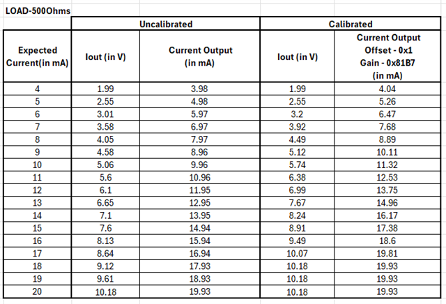
I am working with the DAC8775 in a 4–20 mA output configuration. The output current range is configured correctly, and the DAC output scales linearly. However, the maximum current I’m able to achieve is around 19.3 mA, and I’m unable to drive it up to 20 mA full scale. I have already tried performing gain and offset calibration. For example, when applying calibration, I can see the voltage output increasing proportionally, which indicates that the gain and offset adjustments are taking effect. However, the current output still seems to lock at 19.3 mA and does not go beyond that point.

I have attached the data that I have acquired.

I have listed the configuration of DAC8775 below.

1) Reset Register(0x01) - 0x0001

2) Reset Config Register(0x02) - 0x0012

3) Select Buck-Boost Converter Register(0x06) - 0x000F

4) Configuration Buck-Boost Register(0x07) - 0x061F

5) Select DAC Register(0x03) - 0x0020

6) Configuration DAC Register(0x04) - 0x100C

7) DAC Data Register(0x05) 

I have attached the schematics below:

Could you please suggest possible causes?

Regards,

Nithin D

  • Hi Nithin,

    Can you confirm what you are using for supply voltages? What load are you driving the current into when you take the measurement? Can you measure the voltage on the IOUT pin during this test? IE. are you limited by supply headroom because your load is too large? If your supply is ~15V but you are driving a ~750Ω load, you might be supply limited (~20mA×750Ω = 15V).

  • Hi Paul,

    The supply voltage used is 24V. I have attached the schematic below for reference.


    For testing, I have used both 500 Ω and 1 kΩ load resistors, and in both cases, the output current behavior remains the same.

    I have also shared the corresponding IOUT readings below.

    Regards,
    Nithin D

  • Hi Nithin,

    To start, lets focus on the non-calibrated value.  A few things I would like clarified:

    1. How are you measuring your output current? If you are using a shunt resistor and converting from voltage to current, then we need to make sure your shunt resistor is calibrated.  You are measuring about 0.4% error at full scale current, so we need to ensure the shunt has less error than that target.

    2. Please measure your REFIN voltage.  Reference error will compound with gain error to increase your total error.  We specify the TUE for the 4-20mA as 0.2%FSR with external reference.  We also have a separate error specification for the reference.  When using the internal reference you can see a greater total TUE as the reference error contributes to IOUT gain error.  We specify a typical value of IOUT TUE with internal reference as 0.5%FSR across all temperature.  For that reason, you might be seeing the expected total error.

    Note that our calibration function is only a digital calibration.  So using a large, positive calibration coeeficient will not enable a greater fullscale IOUT value.  In that case, you would need to select a super-set range or overrange function in the voltage output mode.  For example, our 3.5mA to 23.5mA range would enable to calibrate both the endpoints in a 4-20mA functional output span.

    Thanks,

    Paul