This thread has been locked.

If you have a related question, please click the "Ask a related question" button in the top right corner. The newly created question will be automatically linked to this question.

Doubt on Delta Sigma Modulators

Other Parts Discussed in Thread: ADS1204, ADS1203, ADS1202, AMC1210

I am Jyothi, an MTech student from India. 3 of my friends and myself are trying to design a Delta Sigma modulator as part of our course work.

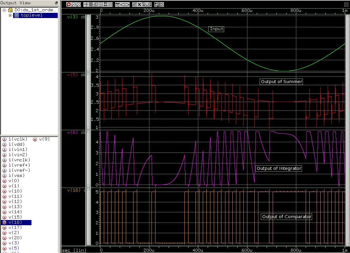
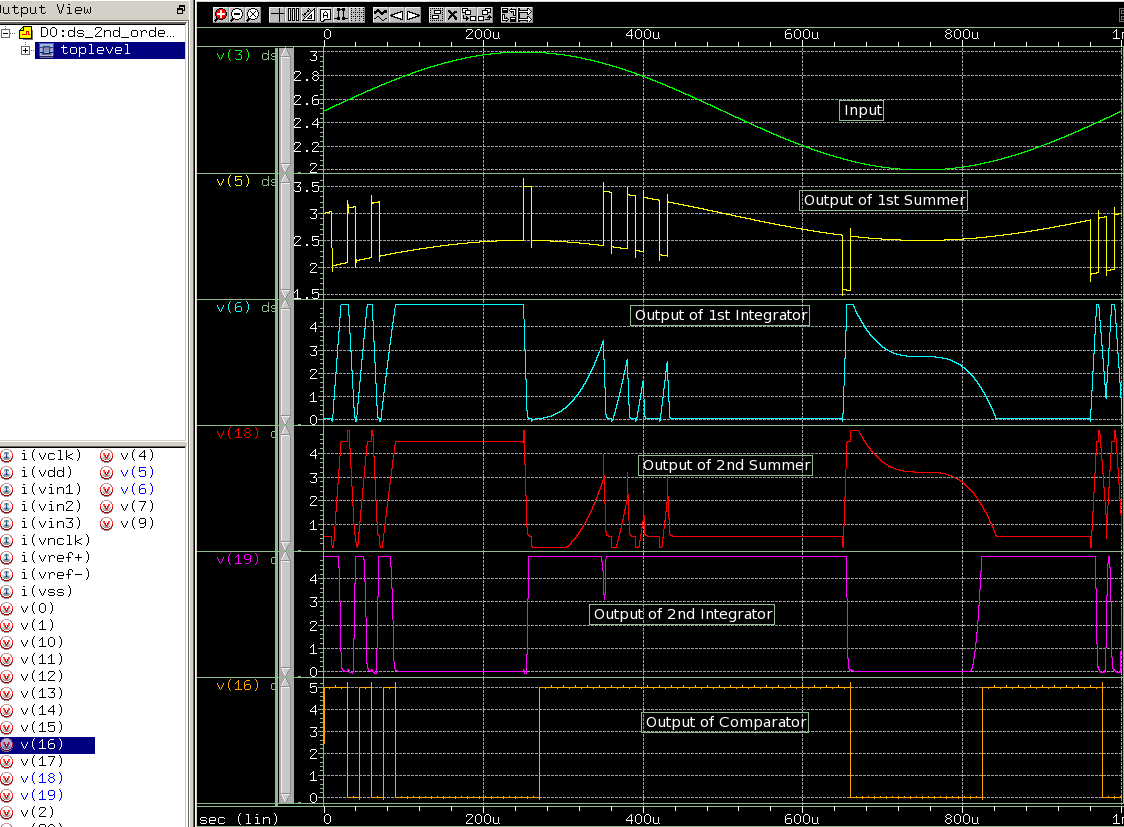
We are doing the CMOS implementation of the circuit using HSPICE tool.  We have completed the first order modulator design and we are trying to do the second order design now.

We have obtained a bitstream from the second order modulator, which is different from the bitstream obtained from the first order modulator. As per circuit diagram, we expect it to be different, but just wanted to confirm this.

Are we expecting exactly same bitstream as output from both 1st order & 2nd order or will they be different?

Please help us understand the difference between the first & second order modulator outputs.

  • Hi Jyothi,

    Welcome to the e2e forum!  Your project sounds interesting!  Can you tell us a little more about how you are looking at the bit-stream outputs?  Assuming that both the first and second order modulators are being clocked the same way, the density of ones/zeros should be the same.  With an analog input at 50% of your full scale range, you should have an output that looks like a square wave with roughly a 50/50 duty cycle with either the 1st or 2nd order modulator.  If you are looking at the output spectrum, you should see difference.  Take a look at this application note which might help you to understand the difference.

    http://www.ti.com/general/docs/lit/getliterature.tsp?literatureNumber=sbaa094&fileType=pdf

    The app note above is based on the ADS1202, which is a second order D-S modulator used in current shunt applications.  The ADS1203 and ADS1204 are similar devices with different input voltage ranges.  You might take a look at the AMC1210 as well which implements various digital filter techniques for these D-S modulators allowing you to use up to four bit-stream input channels.

  • Hi Tom,

    Thanks for the mail. Actually, we are looking at the bitstream output of the latched comparator of DS modulator. Input was a sine wave of 1KHz frequency and peak-peak amplitude of 1V centred at 2.5V for a supply of 0-5V. We have oversampled at 64KHz.  We have taken DC bias of the MOS circuit as 2.5V.

    We have tried both 1st order and 2nd order and we observe different output bitstream at the latched comparator output. Are we wrong? We have not checked the output spectrum.

    Can you tell us what is the kind of output you are expecting for the above specifications we mentioned. Also, can you kindly tell us how to measure the noise spectrum as shown in Fig. 5 in the app note you have shared (http://www.ti.com/general/docs/lit/getliterature.tsp?literatureNumber=sbaa094&fileType=pdf)  We are using the HSPICE tool for our experiments.

    Thanks a lot.

    Warm Regards,

    Jyothi


  • Hi Jyothi,

    It's difficult to say.  You're at 20% max input range so the data is going to be toggling - maybe you can send us a screen shot of your bitstream(s)? 

  • Hi Tom,

    Sorry for this very late reply. We had vacations for 2 weeks. Thats why.  Attaching the output waveforms of both first order and second order DS modulator, that we obtained. We doubt if the problem is with the gain of the integrator. Please Help.

    Output of First Order DS Modulator

    Output of Second Order DS Modulator

  • Hi,

    We were able to do the Delta Sigma modulator correctly and now we have the bitstream which has been successfully filtered using analog filter to get back the input.

    We had some queries on the Digital Filter to be used. What kind of digital filter should be used in the Delta Sigma ADC? We have tried a conventional FIR filter using Hanning Windowing Technique, but this results in filter coefficients to be very very small, which maybe the reason for getting a distorted output. Is this not the right way? Should we go for other types of filters such as Sinc3 filter. We have a 1KHz input signal which is oversampled at an OSR=300. We are a bit confused here and do not know how to proceed. Using an Analog filter, we are getting back our input, but, digital filter is not working. Please help.
    Thanks,
    Jyothi