This thread has been locked.

If you have a related question, please click the "Ask a related question" button in the top right corner. The newly created question will be automatically linked to this question.

ADS8355: DESING CORRECTNESS

Part Number: ADS8355
Other Parts Discussed in Thread: ADS8354

We are using the ADS8355 ADC for one of our applications. In the first configuration, the differential output from the magnetic sensor is converted to single-ended signals, which are then routed to AINP_A and AINP_B for simultaneous sampling. The signal swing in this case is from 0.5V to 4.5V, with the ADC reference voltage set to 5V, along with AVDD and DVDD.

Alternatively, we are exploring the use of the ADC’s pseudo-differential input feature. The magnetic sensor provides differential outputs: SIN+ / SIN- and COS+ / COS-, each swinging between 1.75V and 3.25V. In this configuration:

  • SIN+ is connected to AINP_A
  • SIN- to AINM_A
  • COS+ to AINP_B
  • COS- to AINM_B

We kindly request you to review the ADC section of the design and share your comments or suggestions.
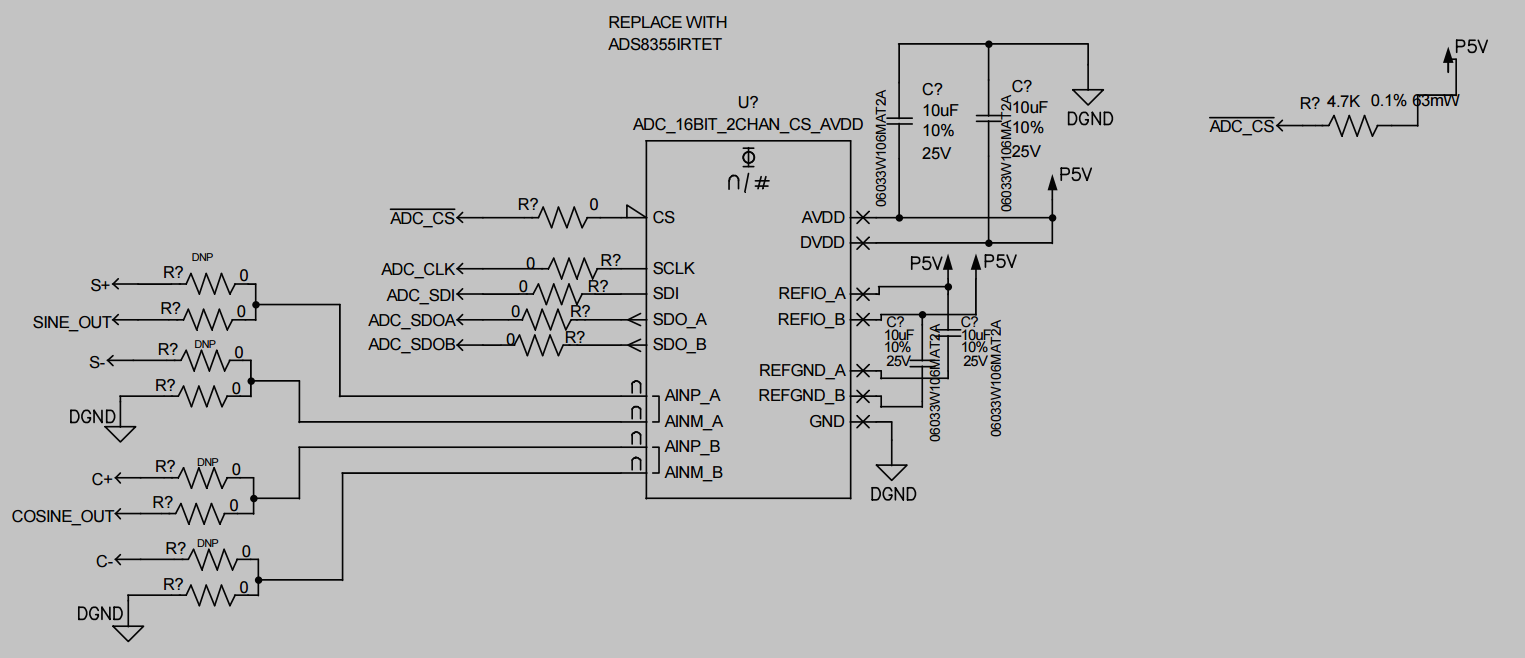
image.png

  • Hello Ayyappan,

    I have a few questions: 

    • Before S+, S-, SINE_OUT, C+, C-, COSINE_OUT, are there ADC Drivers? i.e some sort of opamp or amplifier that can drive the signal into the ADC?  to ensure the full dynamic range of the ADC is used, this is recommended. 
    • As far as the configurations available for ADS8355
      • For Single-Ended mode:
        • AINP: signal input  (an ADC Driver for the signal still recommended) 
        • AINM:GND 
      • For Pseudo-Differential Mode:
        • AINP: signal input  (an ADC Driver for the signal still recommended)
        • AINM: FSR/2  (DC input)
    • The configuration you mention: 
      • [quote userid="629770" url="~/support/data-converters-group/data-converters/f/data-converters-forum/1579796/ads8355-desing-correctness"]
      • SIN+ is connected to AINP_A
      • SIN- to AINM_A
      • COS+ to AINP_B
      • COS- to AINM_B
      • Would require a Fully Differential input configuration. The ADS8355 does not have this capability, it can only do Single-Ended or Pseudo Differential.
      • For a Fully Differential SAR ADC could I interest you in the recently released ADS9327? 
    • Sharing P5V for all supplies should work, but also using the same resource without any additional filtering for the REFIOs could introduce some noise. If possible I would recommend
      • a separate low-noise source for the reference , or
      • a low noise buffer between the P5V and the REFIOs, or
      • at least a way to isolate and filter some noise between the supply and the REFIO pins (like some RCs or a ferrite bead)

    Best regards, 

    Yolanda

  • Hello Ayyappan,

    I have a few questions: 

    • Before S+, S-, SINE_OUT, C+, C-, COSINE_OUT, are there ADC Drivers? i.e some sort of opamp or amplifier that can drive the signal into the ADC?  to ensure the full dynamic range of the ADC is used, this is recommended. 
    • As far as the configurations available for ADS8355
      • For Single-Ended mode:
        • AINP: signal input  (an ADC Driver for the signal still recommended) 
        • AINM:GND 
      • For Pseudo-Differential Mode:
        • AINP: signal input  (an ADC Driver for the signal still recommended)
        • AINM: FSR/2  (DC input)
    • The configuration you mention: 
      • SIN+ is connected to AINP_A
      • SIN- to AINM_A
      • COS+ to AINP_B
      • COS- to AINM_B
      • This would require a Fully Differential input configuration. The ADS8355 does not have this capability, it can only do Single-Ended or Pseudo Differential.
      • For a Fully Differential SAR ADC could I interest you in the recently released ADS9327? 
    • Sharing P5V for all supplies should work, but also using the same resource without any additional filtering for the REFIOs could introduce some noise. If possible I would recommend
      • a separate low-noise source for the reference , or
      • a low noise buffer between the P5V and the REFIOs, or
      • at least a way to isolate and filter some noise between the supply and the REFIO pins (like some RCs or a ferrite bead)

    Best regards, 

    Yolanda


  • Hi Yolanda, 

    This is one of the sineoutput from magnetic sensor, Here Sine_out is single ended swing from 0.5 to 4.5V, and S+,S swing from 1.75 to 3.25 with 180 shift.

    So does pseudo differential mean, needs a fixed DC source?

    Regards

    Ayyappan A

  • Hello Ayyappan,

    Thank you for sharing the schematic, it is very helpful!

    The Pseudo Differential would need a DC source on the AINM pin, it could also be connected to the VREF or a VREF/2 source. 

    It could also be used in Single Ended configuration and the AINM can also just be grounded. 

    Do the SINE+/- and COSINE+/- also have a similar signal chain? do they also have a single ended output? or are these differential signals? 

    Best regards, 

    Yolanda 

  • Hello Yolanda

    The sine and cosine outputs from the magnetic angular position sensor follow similar signal patterns. I understand that pseudo-differential signals typically consist of one varying signal and another reference signal (either fixed at Vref or Vref/2).

    In my application, I’m using an ADC to capture sine and cosine signals from a magnetic sensor operating at a frequency of 2 Hz. The ADC in use is the ADS8355, which supports a sampling rate of up to 1 MSPS. I would like to understand if this high sampling rate could introduce any concerns, particularly regarding noise capture. Additionally, is it possible to adjust or reduce the sampling frequency to better match the sensor’s output frequency?

    My master device supports only a single MISO line, whereas the ADS8355 provides two serial data outputs: SDOA and SDOB. I would like to know:

    • If I operate the ADS8355 in single SDO mode, will simultaneous sampling of both channels still be possible?
    • Alternatively, is it feasible to connect SDOA to the master’s MISO line and SDOB to a GPIO pin on the master for manual data handling or monitoring?

    I also noticed that the ADS8354 supports fully differential inputs, which would allow direct connection of the sensor outputs (Sine+, Sine− and Cos+, Cos−) through RC filtering circuits. Could you please confirm if this configuration would be more suitable for my application?

    Thanks and Regards

    Ayyappan A

  • Hi Yolanda

    We are waiting for your replay.

    Regards

    Ayyappan A

  • Hello Ayyappan,

    Thank you for your explanation, it is very helpful! 

    To answer your questions: 

    I would like to understand if this high sampling rate could introduce any concerns, particularly regarding noise capture.

    It can, but it can be mitigated. Primarily, using a higher speed ADC would require a more robust ADC driver capable of handling the wider bandwidth of the ADC's Nyquist. The ADC will also capture the noise of the Nyquist bandwidth range as well. But this can be mitigated without much issue, by adding anti-aliasing and/or a low pass filter to the signal chain (which is typically recommended for driving a SAR ADC). A low pass filter can be implemented either in the ADC driver, or through the input RC used for the ADC. Additionally having the extra sample speed does bring additional benefits like the possibility of averaging, which can drastically reduce noise and precision of the measurement. 

    Additionally, is it possible to adjust or reduce the sampling frequency to better match the sensor’s output frequency?

    Yes, the sampling frequency can be reduced to better fit the input signals frequency and to reduce the need of the robust driver. I would still recommend the RC but it can also be more simple if the ADC has a longer acquisition time to capture the data. 

    If I operate the ADS8355 in single SDO mode, will simultaneous sampling of both channels still be possible

    Yes, the ADC captures both of the inputs at the same time, but the actual data throughput will be delayed when using a single SDO. The delay happens at the data out and not the data capture. 

    Alternatively, is it feasible to connect SDOA to the master’s MISO line and SDOB to a GPIO pin on the master for manual data handling or monitoring?

    This depends on the controller used, but if the controller is able to collect data and convert it I don't see why this wouldn't work. Typically controllers have some integrated SPI modules, which might make this difficult though. 

    I also noticed that the ADS8354 supports fully differential inputs, which would allow direct connection of the sensor outputs (Sine+, Sine− and Cos+, Cos−) through RC filtering circuits. Could you please confirm if this configuration would be more suitable for my application?

    Yes it will, the ADS8354 would be a good option for a fully differential counterpart to the ADS8355

    Best regards, 

    Yolanda