This thread has been locked.

If you have a related question, please click the "Ask a related question" button in the top right corner. The newly created question will be automatically linked to this question.

TSW14J58EVM: ADC data readout with JMODE8

Part Number: TSW14J58EVM
Other Parts Discussed in Thread: ADC12QJ1600, ADC12QJ1600EVM

Dear TI team,

we are trying to readout the ADCs using the  ADC12QJ1600 and TSW14J58EVM evaluation boards with JMODE8. We are using the lidar_ref_code python sofware to configure the ADC with JMODE8. Configuration looks succesfull :

There are 4 connected devices.

{'index': 0, 'flags': 2, 'type': 7, 'id': 67330065, 'location': 305, 'serial': b'FT4N0ZG8A', 'description': b'ADC12QJxx00RD A'}

{'index': 1, 'flags': 2, 'type': 7, 'id': 67330065, 'location': 306, 'serial': b'FT4N0ZG8B', 'description': b'ADC12QJxx00RD B'}

{'index': 2, 'flags': 2, 'type': 7, 'id': 67330065, 'location': 307, 'serial': b'FT4N0ZG8C', 'description': b'ADC12QJxx00RD C'}

{'index': 3, 'flags': 2, 'type': 7, 'id': 67330065, 'location': 308, 'serial': b'FT4N0ZG8D', 'description': b'ADC12QJxx00RD D'}

***************************************************************************

        Initializing ADC12QJ1600 instance with defined attributes

        Got Init Bit

        ADC device initialization complete successfuly

        ADC is ready for programming

***************************************************************************

***************************************************************************

        Initializing ADC12QJ1600 instance with defined attributes

        Got Init Bit

        ADC device initialization complete successfuly

        ADC is ready for programming

***************************************************************************

P = 2, V = 4, N = 20, FVCO = 8000000000.0

Setting the ADC's JMODE to 8

P = 2, V = 4, N = 20, FVCO = 8000000000.0

Setting the ADC's JMODE to 8

Done

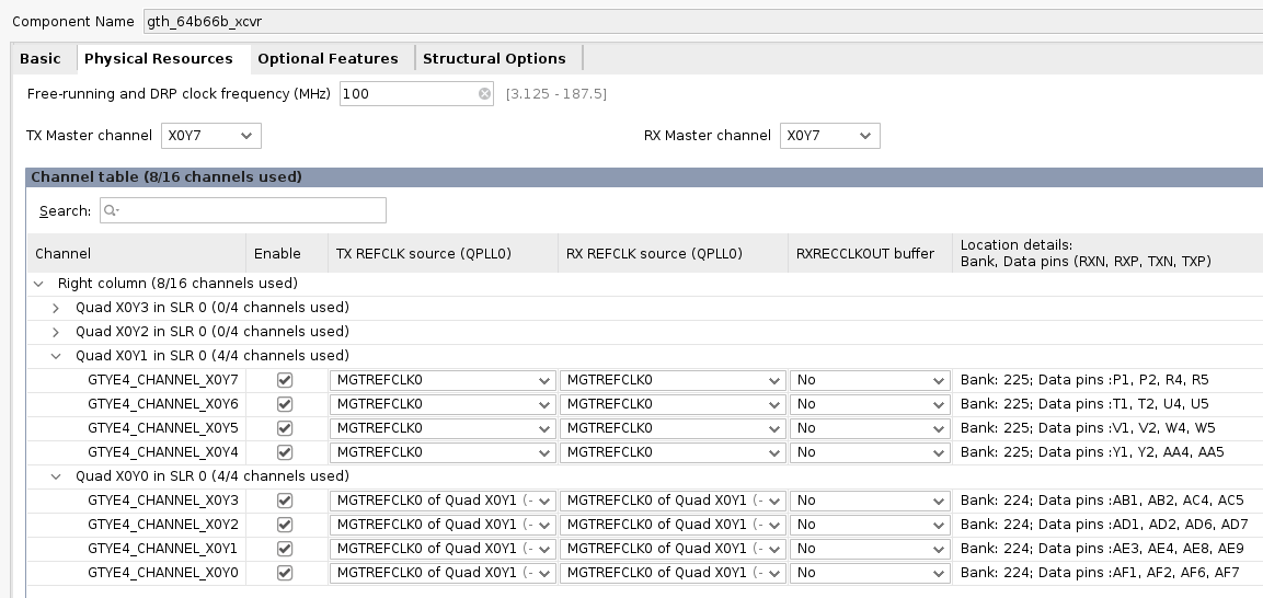
MGTs are configured for 12.375 Gbps with a reerence clock of 193.59375 MHz:image.png

image.png

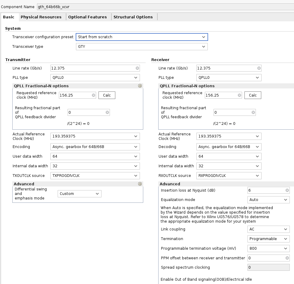
Now looking at the VIO the QPLLs are locked:
image.png

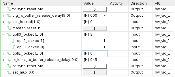
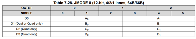
and data are coming out of the ADCs (64bits in every clock cycle) but the final vectors (adc_ch_i_4b192 and adc_ch_q_4b192) output 192 bits in every extended multiblock (ILA inside the refdesign_rx.sv):


image.png

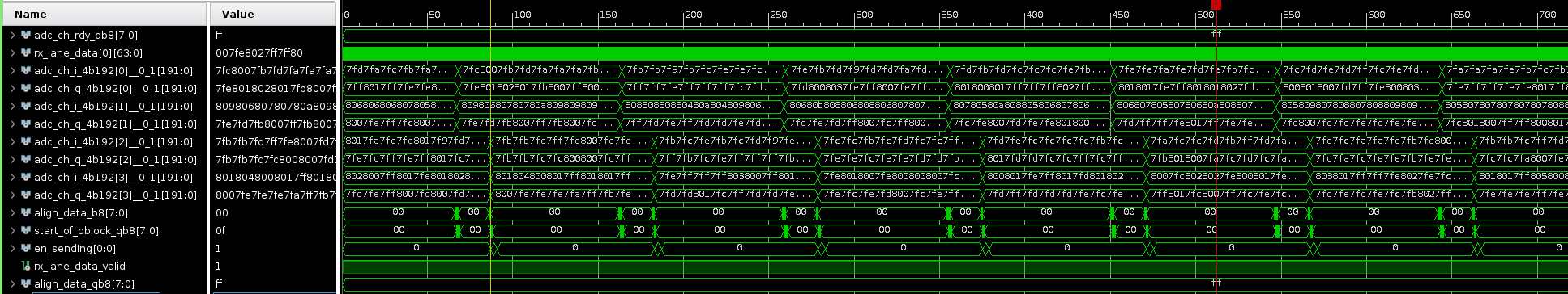
Why we have only 192 bits in every extended multiblock? I would expect 3*32*64 bits (3 emblocks*32 multiblocks*64 bits block). We tried to plot the rx_lane_data(0) data for a 100mv peak to peak sine wave of 1 MHz and we are getting the following:

image.png

where even the amplitude is wrong. We are using the following paramemters on the gteware
: IP_64B66B,  ADC_RESOLUTION=12, NUMBER_OF_RX_LANES=8, NUMBER_OF_QUADS=2,  RX_LANE_DATA_WIDTH=64 and RX_E_VAL=3). 

For sure we are missing something important but could you please help us to solve this?

Thank you in advance,

Panos

  • Sorry I forgot to mention that we are using the TI JESD204 IP core for this

  • Hi I narrowed down the issue. The IP core was modified by a colleague and I wasn't aware of. My question now is: for the JMODE8 do we have to use 1 IP core with lines=8 and the quad=2 or 1 IP core with lines=4, quad=1 as per vcu118_64b66b_2 reference design?

  • Hi Panagiotis,

    Please check the data format setting of the ADC and how what is expected to be captured.

    From the channel capture plot above you can see the format of the data capture is incorrect.

    That would be one thing to try.

    Regards,

    Rob

  • Dear Rob,
    thank you. I am injecting a sinewave at the input of the first ADC (INA0 on the TI balun mezzanine). I verified the ADC configuration with the HSDC software and I can see the sinewave.

    My question is which signal and samples are associated with this input in JMODE8. In the refdesign_rx.sv every 2 lanes are linked to 1 channel I and Q:


    assign ch1_I_samples[i]   = rx_lane_data[0][63-16*i -: ADC_RES];
    assign ch1_Q_samples[i] = rx_lane_data[1][63-16*i -: ADC_RES];
    assign ch2_I_samples[i]   = rx_lane_data[2][63-16*i -: ADC_RES];
    assign ch2_Q_samples[i] = rx_lane_data[3][63-16*i -: ADC_RES];
    assign ch3_I_samples[i]   = rx_lane_data[4][63-16*i -: ADC_RES];
    assign ch3_Q_samples[i] = rx_lane_data[5][63-16*i -: ADC_RES];
    assign ch4_I_samples[i]   = rx_lane_data[6][63-16*i -: ADC_RES];
    assign ch4_Q_samples[i] = rx_lane_data[7][63-16*i -: ADC_RES];

    I am using 2 ADCs, JMODE8, 8 lanes (4 per ADC with 1 IP core and 8 lanes/2 quads) and I would expect 8 ADC channels. How it works in this case? 
    Finally at the TI IP core datasheet there is a mapping of the samples but for JMOD0 and JMODE30, what about JMODE8?

    Thank you in advance,

    Panos

  • Hi Panos,

    When you mention 8 ADC channels, are you using the TSW12QJ1600 EVM reference design? Or are you using the TI ADC12QJ1600EVM itself?

    Or please send a picture so we know what EVM you are working from.

    Thanks,

    Rob

  • Dear Rob,


    we are using all 3 evaluation boards from TI. The TSW14J58EVM (DC182_A9), ADC12QJ1600EVM (REV E2) and ADC12QJ1600 BALUN PCB (REV E4). I have configured the IP core for 8 lanes and the ADCs with JMODE8 but I have connected only 1 channel (INA0) to the generator. My question is how we extract the samples from this channel. Are the data from INA0 associated with rx_lane_data(0)? Is this formula to extract the samples correct: rx_lane_data[0][63-16*i -: ADC_RES] for JMODE8 and resolution of 12 bits?

    thank you in advance,

    Panos

  • Hi Panos,

    After re-reading this, I think there is some confusion. The QJ1600 does not have a DDC and therefore does not output IQ data. Everything you are receiving is real data. Also,  every 2 lanes are linked to 1 channel I and Q” is not correct.


    The bus is packed as data[channel][sample] so for 8 lanes, you would get 8*64*3 bit per cycle, therefore, you would have a 1536 bit bus, or 192 bits per lane and each lane has the samples packed as shown in the picture above. Therefore, each cycle you would get 16 samples.

    Regards,

    Rob

  • Dear Bob,

    thank you for the clarification about the DDC. The output of the MGT is 64 bits so per clock cycle (userclk2) I will have in total 64bits * 8 lanes = 512 bits. I don't fully understand why you say 1536 bits but also the table since it has only 2 samples. Is it correct to concatenate the bits every 3 clock cycles (64 * 3 = 192 bits) aligned at the emblock pulse on sample A0 and then I have an integer multiple of samples (16 samples) as it shown in the attached picture? Different colors correspond to different 64bit inputs


    Thank you in advance,

    Panos