


Part Number: ADS1219
Hello TI,
I have a ADS1219IRTER that does not appear to be working properly. I have the ADC connected to a STM32F446RE and am trying to read the voltage across AIN0 and AIN1. After sending the ADC Start Sync command (0x80) I consistently get an ADC value that is incorrect and does not change even when the input (AIN0 - AIN1) is changing. The ADC inputs are connected to a simple voltage divider that attenuates the output voltage of a custom push-pull converter. The output voltage of this push-pull converter varies but can be set anywhere from 0.6V to 1kV depending on the duty cycle of the STM32. Schematics of the setup are shown below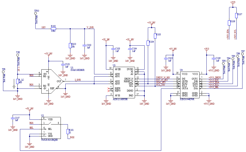
C201 is powered from a 5V lab power supply.
TP3 -> PB5 (GPIO Pin).
TP6 -> PB8 (I2C1 SCL)
TP4 -> PB6 (Contantly set high)
TP7 -> PB7 (Constantly low)
TP5 -> PB9 (I2C1 SDA)
C106 gets power from the STM32 development board.
The main function is the STM32 is simple.
- Configures HAL
- Configures UART (MODBUS)
- Configures PWM via Two Timers
- Configures I2C for the ADC.
int main(void)
{
	//Vars
	eMBErrorCode eStatus;

	//0. Initialize HAL
	HAL_Init();
	//1. System Clock Config
	SystemClock_Config();

	//2. GPIO Config
	//a. UART
	MX_GPIO_Init();
	HAL_Delay(10);
	//b. PWM
	MX_PWM_GPIO_Init();
	HAL_Delay(10);
	MX_TIM5_Master_Init();
	MX_TIM2_Slave_Init(420);
	//c. I2C for ADC
	MX_I2C_GPIO_Init();
	MX_I2C1_Init();
	ADC_RST_HIGH();

	//d. Configure ADC
	//set_adc_gain(1);
	//set_adc_mux(3);
	//set_adc_sps(20);
	//set_adc_cm(true);
	//set_adc_vref(false);
	//tx_adc_wreg();
	tx_adc_start_sync();

	//uint8_t config = rx_adc_rreg(0x0);

	//3. PWM Timer Init
	pwm_start();
	HAL_Delay(100);

	//4. I2C Test
	//rx_adc_count();

	//5. MODBUS
	//a. Initialize
	eStatus = eMBInit(MB_RTU, 0x0A, 0, 38400, MB_PAR_NONE, 1);
	usRegInputBuf[0] = 1;  /* Initialize counter */
	usRegInputBuf[1] = 0;
	usRegInputBuf[2] = 0;
	usRegInputBuf[3] = 0;

	//b. Enable the protocol stack.
	eStatus = eMBEnable();

	//c. Handle Errors
	if( eStatus != MB_ENOERR )
	  {
		  Error_Handler();
	  }

    /* Loop forever */
	for(;;)
	{
		(void)eMBPoll();
	}
}
I am triggering the STM32 to read adc values in a MODBUS callback function,
eMBErrorCode
eMBRegInputCB( UCHAR * pucRegBuffer, USHORT usAddress, USHORT usNRegs )
{
    eMBErrorCode    eStatus = MB_ENOERR;
    int             iRegIndex;

    //0. Sensor Type -> (0x01)
    //a. Check the register limits.
    if( ( usAddress == 0x01 ) && (usNRegs == 0x02 ) )
    {
        //ModBus Standard Packet Size is Two Bytes or a Unsigned Short
        //Smallest packet sends two bytes.
        //i. Move to the next packet frame. -> Assign 0x00;
        *pucRegBuffer++ = (UCHAR)(0x00);
        //ii. Move to the next packet frame. -> Assign 0x49 or "I".
        *pucRegBuffer++ = (UCHAR)(0x49);
    }
    //1. Current Input Register -> (0x02 to 0x04)
    //a. Check the register limits.
    else if( ( usAddress >= 0x02 ) && ( usNRegs == 0x02 ) )
    {
        //b. Get the current.
        g_f_current = get_voltage();
        //c. Convert float to ushort.
        modbus_set_float_us(g_f_current, &test_float_us);
        //iRegIndex = ( int )( usAddress - usRegInputStart );
        iRegIndex = usNRegs-1;
        //d. Copy current to ModBus Input Regs.
        while( usNRegs > 0)
        {
            *pucRegBuffer++ = (UCHAR)(test_float_us[iRegIndex] >> 8);
            *pucRegBuffer++ = (UCHAR)(test_float_us[iRegIndex] & 0xFF);
            iRegIndex--;
            usNRegs--;
        }
    }
    else
    {
        eStatus = MB_ENOREG;
    }
    return eStatus;
}
The function get_voltage() calls rx_adc_count(),
float get_voltage()
{
    int32_t adc_count = rx_adc_count();
    float voltage = 0;
    if (g_enum_gain == one)
        voltage = (float)(adc_count*(2.0f*2.048f/1.0f)/16777216.0f);
    else
        voltage = (float)(adc_count*(2.0f*2.048f/4.0f)/16777216.0f);
    return voltage;
}
nt32_t rx_adc_count()
{
uint8_t adc_p[3];
uint8_t i2c_data = ADC_RDATA;
HAL_I2C_Master_Transmit(&hi2c1, SLAVE_ADDRESS, &i2c_data, 1, 10);
HAL_I2C_Master_Receive(&hi2c1, SLAVE_ADDRESS, &adc_p[0], 3, 10);
g_rx_adc_count = adc_p[0] << 16 | adc_p[1] << 8 | adc_p[2];
uint8_t pol_bit = g_rx_adc_count >> 23;
if (pol_bit == 0)
{
g_rx_adc_count_signed = g_rx_adc_count;
}
else
{
g_rx_adc_count_signed = g_rx_adc_count;
g_rx_adc_count_signed = g_rx_adc_count_signed - 16777216;
}
return g_rx_adc_count_signed;
}I have verified the data that is being received by the STM32 is correct by looking at the I2C bus on the scope.

The issue is the ADC count does not change when the voltage on the input changes.
Does anyone have any suggestions on what I am doing wrong?
Thanks,
Allan

