This thread has been locked.

If you have a related question, please click the "Ask a related question" button in the top right corner. The newly created question will be automatically linked to this question.

ADS9226: ADS9226 sometimes outputs zero data on startup

Part Number: ADS9226
Other Parts Discussed in Thread: THP210

We have been using ADS9226 for some time now, and we occassionally see cases where the part will output zero data (i.e. all data lines = '0') after a power cycle.  Sometimes this affects both channels, other times only one channel.  The data sheet does not recommend any particular power rail sequence, but we find that it prefers to have the analog 5V rail up first followed by the digital 3V3 rail.  The only way to recover correct operation is to completely power cycle the part.   This is our schematic:  

image.png

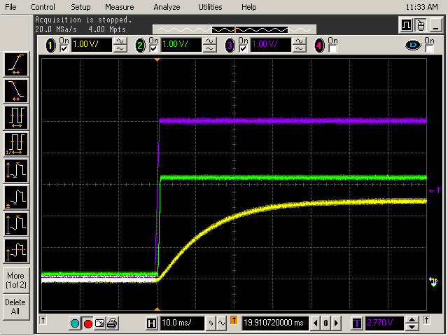
and our power sequencing looks like this:    
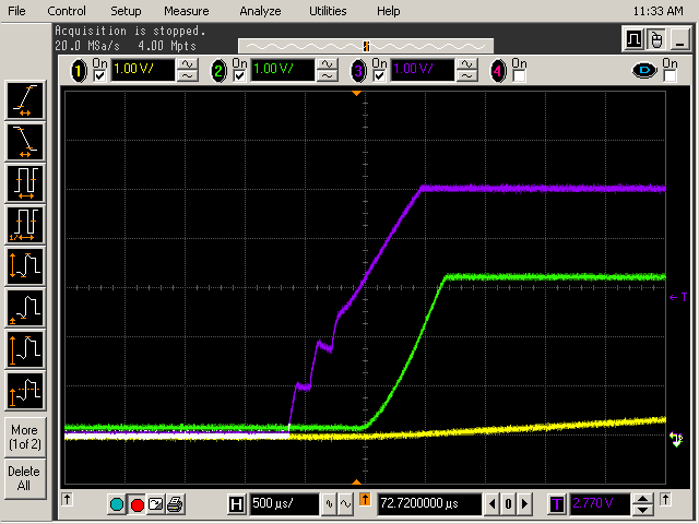
image.png

Blue = AVDD (5V) Green = DVDD (3V3) Yellow = REFIN (2V5) all measured at the device pins.  

Is this a known issue?   Do you have any recommendations for how we can make the startup more reliable?   

  • Hello Murray, 

    Apologies for the delay, I was out of office. 

    Could you please share the schematic including the ADC drivers used? I see the capacitors of the input RC are not populated, is there a reason for this? 

    Could you also measure what the input common mode is? (AINP-AINM)/2, or at least the voltage at AINM? 

    What external reference is being used? does is share the supply with the ADC?  is it able to drive the 1kΩ and 10uF? it also seems to be taking some time to reach the 2.5V 

    Best regards, 

    Yolanda 

  • Hi Yolanda

    Thanks for the reply.

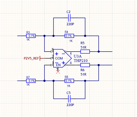
    The ADC inputs are driven by THP210 fully-differential opamps which are powered from the same 5V rail used to power the ADC AVDD pin:

    We had issues with code jumps around zero when the ADC input RC capacitors were fitted.  Removing them resolved this.  

    Common mode input voltage is 2.5V.  This is defined by the COM pin of the THP210 driver amp which is connected to the same external 2.5V reference used for the ADC.

    External reference is LTC6655LN.  It is supplied from a separate regulator.  The slow rise time is due to the RC filter time constant, and also the iternal filter time constant of the reference.  Here is the power sequence using a slower timebase:

    Blue = AVDD (5V) Green = DVDD (3V3) Yellow = REFIN (2V5) all measured at the device pins.

  • Hello Murray, 

    Is there any way that the digital communication with the device starts before the supplies or external reference are fully ramped when the issue is seen? 

    Could the the AINM voltage be measured as well? it should be Vref±100mV

    Best regards, 

    Yolanda

  • Hi Yolanda

    Yes, both CS_n and SCLK will be active as the supplies and reference ramp up.  Could this be the cause of our startup issue?  If so, what state should they be kept in whilst the supplies are ramping up?

    AINM at startup tracks Vref, but in operation AINP and AINM are driven differentially, i.e. both are biased around Vref, but both are modulated by the signal.  I hadn't spotted in the data sheet that AINM should be limited to Vref+/-100mV, so I'll check whether we are exceeding these limits.  What would be the effect if AINM was exceeding Vref+/-100mV?

    Thanks

  • Hello Murray, 

    When you say active regarding CS_n and SCLK, do you mean they are toggling? If so this could be causing the issue.  A low to high transition does start a conversion, so if the CS could be kept low or at least static until all supplies are ramped up. The device has a wake-up period after power-up before it is fully initialized and conversion can start. That time can vary a bit and it is mostly dependent on the REFP. Adding a small delay of a few ms  after REFP is fully settled to start any digital communication could help. 

    Would it be possible to capture a similar oscilloscope screenshot with one or both of the REFPs?

    Best regards, 

    Yolanda 

  • Hi Yolanda

    The scope trace below shows both REFPs, together with AVDD and CS_n:

    Blue = AVDD, Green/Yellow(overlaid) = REFPs, Pink = CS_n

    So we definately have CS_n toggling before the supplies are up.  It looks like we should be waiting ~50ms before allowing CS_n to toggle.  CS_n is driven from an FPGA, so we can easily add a delay.

    Is REFP at the voltage you would expect (~4.4V when settled) ?

    Thanks

  • Hello Murray, 

    Thank you for sharing the scope shot.  

    The 50ms delay makes sense, and if possible to add that delay it would be ideal. 

    4.4V for RefP sound reasonable, the internal reference buffer has a gain of ~1.75V/V, so with an input reference of 2.5V ~4.375V is expected 

    Best regards, 

    Yolanda