ADC3563: Complex I Q output potentially flipped from ADC?

Part Number: ADC3563


Hi,

We are working with ADC3536 to do IF complex sampling and trying to implement the LVDS interface and are having difficulties with the configuration.

Configuration:

ADC: ADC3536
Sample Clock: 55.296 MHz
IF Frequency: 13.824 MHz
Mode: 2-wire, 20-bit, complex decimation by 4

Register configuration:

Here is the sequency of register writes we perform to configure the devices:

0x07, 0x4B: 20-bit, 2-wire
0x13, 0x01: Load Output Interface
Wait 2 ms
0x13, 0x00: Load Output Interface
0x19, 0x80: Configure FCLK for 2-wire Complex Decimation
0x1B, 0x40: Configure Output Interface Resolution for 20-Bit
0x0E, 0x10: Internal voltage reference and single ended clock input
0x24. 0x06: Enable decimation filter
0x25: 0x20: Complex decimation by 4
0x27: 0x10: Configure complex output
0x2A: 0x00: Configure NCO to 13.824 MHz (0x40000000)
0x2B: 0x00: Configure NCO to 13.824 MHz (0x40000000)
0x2C: 0x00: Configure NCO to 13.824 MHz (0x40000000)
0x2D: 0x40: Configure NCO to 13.824 MHz (0x40000000)
0x26: 0xA0: Set mixer gain, update NCO frequency
0x26: 0x80: Toggle mixer update


Deserialization:

We deserialize using the FCLK as the synchronization pattern:
FCLK: 1111111111 0000000000
DA1 : IIIIIIIIII QQQQQQQQQQ
      D19……………D1 D19……………D1
DA0 : IIIIIIIIII QQQQQQQQQQ
      D18……………D0 D18……………D0


Issue:
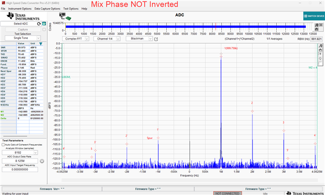
We inject a tone at IF+1 MHz (13.824 MHz + 1.0 MHz) and expect to see a tone at +1.0MHz when performing a complex FFT on the output of the ADC. 

What we see is a tone at -1.0 MHz which would be the case if I and Q are swapped. What is causing the problem. Do we have misconfiguration somewhere? 


  • Update:
    We have it now working with setting the NCO frequency to ofcourse -13.824 MHz and not 13.824 MHz

    We also tried invert the mixer phase in register 0x27 in accordance to chapter 8.3.4.4 but that did not work. Why is that? 

  • Hello,

    I'm glad you were able to get it working. The op_order bit in register 0x27 is not properly documented. It does not quite swap the I and Q data. This bit should be set as it is documented in table 8-7 in the datasheet for proper operation.

    Best,

    Luke Allen

  • Hello,

    Thank you for your answer. Yes I see that. I also meant the "MIX PHASE" register, bit 0 in register 0x25 - That does not seem to do what I expect. I.e. subtract the NCO. 

  • Hello,

    Ah, I see. What you are experiencing (seeing a tone at -1MHz when you are injecting a tone IF + 1MHz) is expected behavior for this ADC. The ADC was designed this way because it simplified the design of the DDC filter. Unfortunately, this is not explained very well in the datasheet. The user must just keep in mind that the output data will be mirrored across the NCO frequency, meaning Fout = -(Fin - Fnco). However, setting the MIX PHASE field in register 0x27 to 1 should mirror the output again, meaning Fout = Fin - Fnco. I set this up in the lab and took a quick (unfiltered) capture just now to verify this behavior. Please see the below images, Fnco = 12MHz, Fin = 11MHz.

    Best,

    Luke Allen

  • Hi Luke,

    Thank you. We just tried again with the Mix Phase inversion and it seems to behave as expected.