This thread has been locked.

If you have a related question, please click the "Ask a related question" button in the top right corner. The newly created question will be automatically linked to this question.

ADS124S08: Review schematic

Part Number: ADS124S08

Hi team,

pls help review the ADS124S08 as below. aslo I want to know as PT100 applicaiton.

I'd like to know if IDAC has any layout considerations regarding its application in the PT100. Thansk 

2pcs ADS124S08 on the board. one for PT100 another for general ADC.
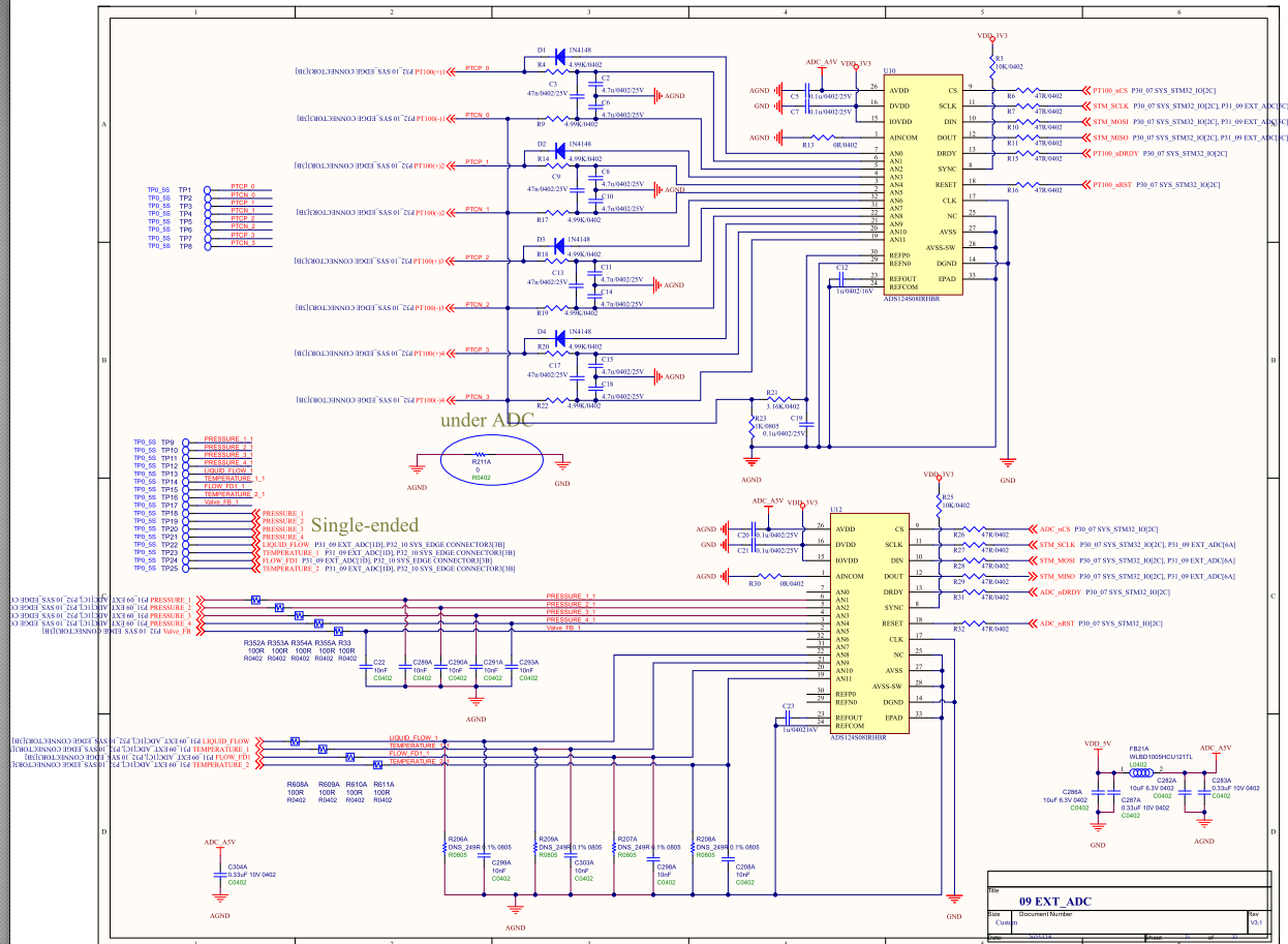
 

image.png

  • Hi Jimmy WANG,

    Can you provide this as a PDF? I cannot read the image, the text is very small. And zooming into the image just makes it blurry

    -Bryan

  • Hi Bryan,

    pls refer.

    ADS124S08.pdf

  • Hi Jimmy Wang,

    Thanks for providing the PDF. Some feedback for you:

    • We generally do not recommend split ground planes i.e. different grounds for AVSS and DGND. I do see that you have a 0ohm resistor connecting the two grounds, but then you have a single point through which all of your currents must flow. Again, our recommendation is to use a solid ground plane instead
    • You need at least 0.33uF capacitance on AVDD. I see that you have some additional caps on the AVDD supply, it is just not clear from the schematic that they will be close to the AVDD pin
    • I would add a pull-up on the RESET pin as well
    • The cutoff frequency on your input filters for the RTDs is a bit low (~300Hz). This is not wrong, just something to keep an eye on in case you run into settling issues. Of course you can always change these components manually during prototyping
    • We don't necessarily recommend diodes on the IDACs for protection, because these will not protect against a negative overvoltage. A current limiting resistor is usually sufficient
    • Make sure the ADC PGA is disabled for the single-ended measurements
    • Pull the START pin low if you are going to control conversions using the START command (since you don't have a connection between the START pin and your controller)
    • I assume you will use the ADC internal reference for the single-ended measurements because there is nothing connected to the external VREF pins on the second ADC

    -Bryan

  • Hi Bryan,

    I'd like to know if IDAC has any layout considerations regarding its application in the PT100.

    • We don't necessarily recommend diodes on the IDACs for protection, because these will not protect against a negative overvoltage. A current limiting resistor is usually sufficient==> The EVM uses the diode to design 
  • Hi Jimmy WANG,

    I am not sure what you mean by "layout considerations". The signals the customer selected are all adjacent to each other so there are no concerns about having to cross difference traces during routing. So I don't see any special considerations here, just follow regular best practices for placement and routing

    Also, I understand that the ADS124S08EVM has diodes. But what I said is still true: the diodes do not protect against negative overvoltages, so a series resistor is typically a better choice.

    -Bryan