This thread has been locked.

If you have a related question, please click the "Ask a related question" button in the top right corner. The newly created question will be automatically linked to this question.

ADC32RF55: JESD lane setting (Continue)

Part Number: ADC32RF55

Hello team,

This is related to my previos thread below.
My customer only use single channel of this ADC, and want to know how to configure JESD lane setting.

https://e2e.ti.com/support/data-converters-group/data-converters/f/data-converters-forum/1535957/adc32rf55-jesd-lane-settings

I understood L=4 lane is possible using JESD page 0x28, after configuring it as 8-2-8-20.

However, does the ADC become L=4 during the ILAS phase of JESD204?
My customer would like to set the FPGA to 4-1-8-20, so ADC should be configured as 4-1-8-20 to pass the ILAS phase. (Should they set the FPGA to 8-2-8-20?)

Also is it possible to achive 3GSPS sampling (bypass mode) by using only 4 lanes of JESD204?

Best Regards,
Kei Kuwahara

  • Hi Kei,

    I'm actually not sure if there is an option to adjust L and M in the ILAS multiframe. I know the device has an option to adjust K and F values, but I am unsure if the other values are supported or not. I will have to check with the designers on this one. Kindle await a response.

    Thanks, Chase

  • Hello Chase-san,

    Thank you for your reply.

    Have you been able to checked with the designer?

    Best Regards,
    Kei Kuwahara

  • Hello Chase-san,

    Have you heard anything back from the designers?

    Best Regards,
    Kei Kuwahara

  • Hi Kei-san,

    Sorry, we are very busy with projects right now. I just got off a call with them. We will have info by tomorrow.

    Thanks, Chase

  • Hi Kei-san,

    Find details of ILAS program settings below. This is for all settings of ILAS multiframe 2 minus the checksum.

    Thanks, Chase

    JESD PAGE:
    
    DID: 0x50[7:0]
    ADJCNT: 0x51[3:0]
    BID: 0x51[7:4]
    ADJDIR: 0x52[6:6]
    PHADJ: 0x52[5:5]
    SCR: 0x53[7:7]
    ILAS_L_M1: 0x53[4:0], L value minus 1
    LID DOUT0: 0x54[4:0]
    LID DOUT1: 0x55[4:0]
    LID DOUT2: 0x56[4:0]
    LID DOUT3: 0x57[4:0]
    LID DOUT4: 0x58[4:0]
    LID DOUT5: 0x59[4:0]
    LID DOUT6: 0x5A[4:0]
    LID DOUT7: 0x5B[4:0]
    ILAS_F_M1: 0x5C[7:0], F value minus 1
    ILAS_K_M1: 0x5D[7:0], K value minus 1
    ILAS_M_M1: 0x5E[7:0], M value minus 1
    CD: 0x5F[7:6]
    ILAS_N_M1: 0x5F[4:0], N value minus 1
    SUBCLASS: 0x60[7:5]
    ILAS_NPR_M1: 0x60[4:0], NPR value minus 1
    JESDV: 0x61[7:5]
    ILAS_S_M1: 0x61[4:0], S value minus 1
    ILAS_HD: 0x62[7:7], HD value
    CF: 0x62[4:0]
    RESERVED1: 0x63[7:0]
    RESERVED2: 0x64[7:0]

  • Hello Chase-san,

    Thank you for the ILAS program.

    So customer can set the L=4, M=1 using this ILAS program?

    Or should customer modify this program?

    Best Regards,
    Kei Kuwahara

  • Hi Kei-san,

    Yes, the customer can put whatever information here as they desire. It only affects multiframe 2 of ILAS during link bringup.

    Thanks, Chase

  • Hi Chase-san,

    Thank you for the information. Customer has 3 questions.

    Question1

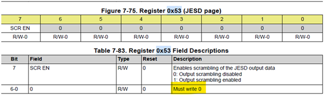
    Looks like we can change the register 0x53 to change the L and M values during ILAS.
    However, on the datasheet, it says 0x53 [6-0] msut be 0.
    Is it okay to change them? Is it okay because it only affects multiframe 2 of ILAS?

    SCR: 0x53[7:7]
    ILAS_L_M1: 0x53[4:0], L value minus 1

    Question2

    Customer is thinking to set below regsiters as these values for setting L=4, M=1.
    Is this correct?

    Register 0x53=0x83
    Register 0x5E=0x00

    Question3

    Is it okay to set JESD mode = 8-2-8-20, even customer only want to use as L=4, M=1?

    Best Regards,
    Kei Kuwahara

  • Hello Chase-san,

    Happy new year!
    Hope you had a wonderfull holidays.

    Can you check the 3 questions above?

    Best Regards,
    Kei Kuwahara

  • Hi Kei-san,

    Please use the info which we received from the designers above and ignore what the datasheet says. I've answered this many times now that there is no single channel LMFS mode and they have to use the 8-2-8-20 mode. Ignore the unused lanes on the FPGA to achieve the single lane operating aspect. Personally I would say for any customer which cares about accuracy of ILAS configuration, that the ILAS configuration should exactly match the converter's actual LMFS. Otherwise down the road someone may actually waste time trying to understand how to put this device into the 4 lane mode, which doesn't exist.

    Thanks, Chase

  • Hello Chase-san,

    Thank you for the clear answer.

    Customer has understood, so I am closing this thread.

    Best Regards,
    Kei Kuwahara