This thread has been locked.

If you have a related question, please click the "Ask a related question" button in the top right corner. The newly created question will be automatically linked to this question.

ADS1220: Flexible temperature sensor AFE

Part Number: ADS1220
Other Parts Discussed in Thread: TMUX1112, ADS122S14, ADS122C14, TPD1E10B06

Hi,

Working on an industrial temperature sensor interface, where the actual temperature sensor is external to the system (wired via connector) and in addition my analog frontend shall be able to support a range of temperature sensors. Actual list of desired sensors are quite long, but from a requirement perspective it boils down to one one end PT100 sensors with temperatures from -40C to +40C (~84 to 115ohms) and on the other extreme NTC 20k sensors where in the same temperature range I get resistance values between ~800k down to 10k.

First questions, I can't find a reference design on ti.com where this has been done and tested - does it exist? If not I need to come up with a new design.

Reading through appnotes and forums it seems solving this for RTDs (PT100, PT1000, Ni1000 etc) is quite straight forward, I've configured these sensor types succesfully with low side R_REF using the excellent excel  tool www.ti.com/.../ADC-RTD-CONFIG-CALC

For now I'm assuing using ADS1220 but that is not a must. Adding support for the NTC sensors is however not quite as straight forward as I hade hoped. With IDAC currents min 10uA I can't use current excitation since the drop across an NTC20k at 800k is then 8V which is completely out of range. So my current thinking is to make a firware configurable AFE that can switch to voltage excitation when using high resistance NTC sensors.

Below is a picture of where I'm at in this process and I'd like some input on some topics here. The idea is to use a 1mA current excitation with a low side R_REF of 1.5k (with PGA enabled) for RTDs but switch to voltage excitation when using NTC thermistors. In voltage excitation mode the low side resistor will then also via switches have a configurable value, and the PGA bypassed. Picture shows two ideas for voltage excitation, either the 5V AVDD supply directly or an external voltage reference source (design not yet complete for this option).

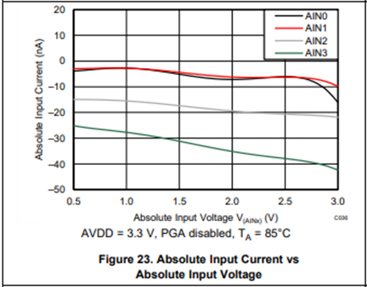
1) Any general concerns regarding this proposal?  Bob Benjamin mentions in another thread on the topic of ADS1220 and NTCs that the input leakage will be the biggest issue here. Device operating temperature is targeting -25C to +50C under which it seems that these leakage currents could be below 5nA on AIN1? We are targeting accuracy on better than 0.3C for high accuracy temperature sensors (PT100 etc) and can likely accept a little worse accuracy in the case of NTC 20k thermistor at 800k (~ -40C).

2) In voltage excitation mode, I assume using a dedicated voltage reference will result in lower ADC  noise compared to using AVDD as reference. It however complicates things quite a bit in terms of switches required. Is it worth at all considering voltage excitation using AVDD and having AVDD as ADC reference in the ADS1220?

3) Using TMUX1112 is an idea for switching in different low-side resistors, due to very low leakage in this switch. Any concerns here?

Thanks in advance!


  • Hello, 

    Your approach is sound, using current excitation for the PT100 and voltage excitation for the NTCs is a good strategy. 

    1. Yes the input leakage could be a factor when measuring the NTCs, on page 12 and 13 in the data sheet there includes some graphs related to this. For an operating temperature of -25C to +50C AIN1 the leakage current should be below 5nA. AIN2 could have a slightly higher leakage current at temperatures >25C (see graphs below from page 13 of data sheet) 

    2. Using an external reference with ADS1220 would be best for the noise performance. AVDD can be used however it does come the possibility of noise of AVDD directly affecting the ADC performance. 

    3. TMUX1112 is an excellent choice for the switching of the low-side resistors. Very low leakage as you mention and a very low on-resistance relative to the low-side resistors you will be using. 

    Additionally, on the low pass RC filter on the REFP0 and REFN0 you can remove the series resistor on the REFN0 and the common mode capacitors. 

    Since you mentioned the ADS1220 is not a must I wanted to share some information about the latest sensor measurement ADC the ADS122S14. This is the next generation of the ADS1220 family of devices. The ADS122S14 has a dedicated REFOUT pins that is a direct output of the internal programmable voltage reference:1.25V or 2.5V which could save you from needing an external reference IC. 

    Features: 

    • Low power consumption (as low a 57µA)
    • Wide supply voltage range:
      • Analog: 1.74V to 3.6V
      • Digital: 1.65V to 3.6V
    • Programmable gain: 0.5 to 256
    • Programmable data rate (up to 64kSPS) and speed mode to trade power consumption and noise performance
    • Simultaneous 50Hz and 60Hz rejection at 20 or 25SPS with single-cycle settling digital filter
    • Analog multiplexer with 8 independently selectable inputs
    • Dual-matched programmable current sources (1uA - 1000uA)
    • Internal programmable voltage reference:1.25V or 2.5V with 25ppm/°C (max) drift
    • Internal 1% (max) accurate oscillator
    • Internal temperature sensor
    • Four general-purpose I/Os (push-pull or open-drain output)
    • SPI-compatible interface with optional CRC and daisy-chain capability

    Regards, 

    Andrew 

  • Hi Andrew,

    Thanks for a very quick response and all details provided. The new ADS122S14 or C14 sure seems like a much better match for my requirements, thanks for highlighting this. Seems this new ADC has a number of improvements which makes my design easier to implement.

    With the IDACs range now supporting down to 1uA I should be able to use current excitation also for the NTC thermistors, removing the need for a voltage divider and voltage excitation completely (?).

    The PGA input voltage range is also extended compared to ADS1220 making it easier to meet input voltage requirements. In addition I get an integrated GPIO expander functionality for controlling my low side switches as well as an I2C interface making it easier to control this ADC over an isolation barrier compared to SPI. I'm targeting ADS122C14 based on this, only concern here is the availability of this part. I will try to put in a sample request and see how that goes.

    Sketch for design now looks like below, one remaining question though:

    With a connector for external sensors ESD protection is a concern. Targeting IEC 61000-4-2 level 4, 8kV contact and 15kV air discharge, I suspect I need some additional external ESD suppressors. Any hints on suitable parts with low leakage for this case? I'd also like to support a user accidentally connecting +/-24V to the sensor connector instead of a temperature sensor. I've simulated ADC internal clamp currents for the case below with the series resistors as show which meets the abs max 10mA input currect requirement with some margin. This case also needs to be considered when selecting external ESD suppressors such that those ESD components also can handle +/-24V at the temp sensor connector. The capacitor at the IDAC output is for filtering overvoltage events, I hope the current sources are stable also with some external capacitance like this?

    Thanks!

  • Hi, 

    The extended range of the IDACs in the ADS122S14 and ADS122C14 would make current excitation possible across both the RTDs and the Thermistors. Based on your response and requirement to cross an isolation barrier the ADS122C14 is a good option for I2C communication. The design you have should work with the current layout. 

    Looking at the ESD protection concern the TPD1E10B06 might fit your system well. The TPD1E10B06 is rated for IEC 61000-4-2 level 4 ESD protection and has a 100nA leakage current maximum which will still impact measurement accuracy, especially while using small IDAC currents. Physically on the PCB it would be best to have these as close to the connect as possible with short traces. With the 2.7kΩ resistors on the analog input this should limit the current, the only concern would be on "RPROTECT" if the 470Ω limits the current enough of the over voltage event. 

    The capacitor on the IDAC output shouldn't have an negative effect, unless you were switching the MUX quickly there would be a settling time concern but, in this application I don't believe it would be a problem. 

    If you have the analog pins available you could also use AIN2 as a differential input pair with AIN1, similar to the design with the ADS1220. This would allow for differential filtering which can significantly improve signal integrity and measurement reliability in harsh industrial settings where electrical noise would otherwise cause temperature reading errors. The current design should still work but this could protect the signal measurement circuit even further. 

    As an option for a first prototype you could also route the REFOUT as an excitation source to give testing options for voltage excitation using a removable 0Ω resistor. This comes with a protection limitation due to a voltage drop over any series resistor introduce to the measurement. 

    If you have trouble getting samples I can also put in a request for you on the backend. 

    Regards,

    Andrew

  • Hi,

    Thanks, I think I have enough information now to get started on prototyping. I will add some additional options for excitation to the first prototype boards, as well as for using additional inputs for a "true" differential configuration. I picked the scheme in my picture above from the "ADS122S14EVM and ADS122C14EVM Evaluation Module schematics", based on figure 2-5 in "SBAU453" my understanding is that I can use REFP/AIN4 as both a differential input to the PGA as well as the positive reference voltage node at the same time (also datasheet chapter 7.3.3.2).

    I do have trouble getting hold of samples, if you could put in a sample request for a couple ADS122C14 to be used for initial prototyping that would be most helpful.

    Thanks!

  • Hi, 

    Yes that is correct you can use AIN4/REFP as an analog input and REFP at the same time. 

    Happy to help you get samples. Would you be able to share the error you are getting on the TI store? This product is new to the store and just want to make sure there aren't any kinks with ordering the team is unaware of. 

    If you'd like to take this offline I can send you an message using the email connected to your MyTI account or you can can "connect" with me by click on my profile. 

    Regards, 

    Andrew 

  • Hi,

    Yes, we take the samples offline. I have sent you a message!

    Marking this issue as resolved now.