This thread has been locked.

If you have a related question, please click the "Ask a related question" button in the top right corner. The newly created question will be automatically linked to this question.

ADS131M06-Q1: DRDY SIGNAL ISSUE

Part Number: ADS131M06-Q1
Other Parts Discussed in Thread: ADS131M06,

Hi, im using ADS131M06, 

word length set to 16bit mode

sample rate set to 32ksps, are able to do, after that im reading the data with drdy falling edge signal,

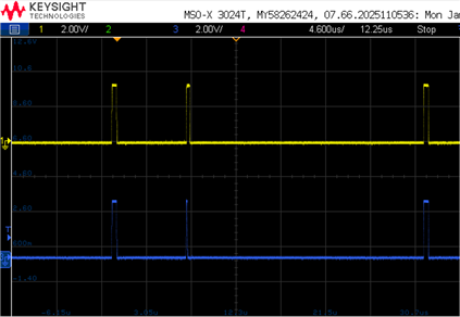
once after drdy falling edge occurs SPI transfer start , data is reading after that in the last crc frame drdy goes high, but again it is becoming low, it should become low in next sample rate only right, but before itself it is become low. what will be the reason.

please find the attached waveforms

yellow =  drdy, blue = chip select , green =  spi clock, in the below image we can see drdy interrupt comes every 32ksps, but in between drdy signal become high and low, i dont know why

image.png

image 2 - zoomed one

image.png

please kindly help us and suggest what to do for this issue.


regards,

srinath

  • Hi srinath,

    Can you please let me know how you read the data? use the /DRDY as an interrupt to your host for reading data or periodically read data in a fixed time delay?

    Did you change register settings including DRDY_FMT bit in the MODE register?

    BR,

    Dale

  • Hi Dale, 

    initially I will do word length settings and sample rate settings, and i will verify the settings by read registers commands by polling mode 

    once it will ok mean. I have some milli seconds delay for other operations, after that for every drdy falling edge (new sample ready) I will read the data with spi dma mode.

    no change did in DRDY_FMT bit in the mode register

    word length mode to 16-bit mode: 0x0410(write data)

    sample rate set to 32ksps: 0x3F02(write data)

    regards,

    Srinath

  • Hi srinath,

    Thanks for your information. Can you share your schematic? Were you sending NULL command (all '0's) to the ADC when you captured the the timing?  What's your SPI clock frequency?

    BR,

    Dale

  • Hi Dale, Thanks

    yes, the TX buffer will always be 0's only, no change in that null command, in a 16bit mode total 16bytes (status +6 channels + crc each 2 bytes) null command will send during SPI DMA transfer.

    As of now our SPI clock frequency is 12.5MHz, after that we planned to increase the clock from 25 to 40MHz.

    please find the schematics below,

    we are not giving any analog input to device, were just checking the communication between MCU and ADS131M06.

    those pullup resistors on sync, cs, drdy, and dout are not mounted.

    actually, this issue is mentioned in the ADS131M06 datasheet section 8.5.1.9.1, regarding this narrow pulse.

    so, one more doubt, during the continuous reading if we toggle the sync/reset pin it will reset the whole device or only the FIFIO buffer data.

    and one more thing, this maybe you have already known, in the ADS131M06 datasheet register sections, CLOCK register reset value should be 0x3F0E, but it is given as 0x7F0E,

    regards,

    Srinath

  • Hi srinath,

    I will check the details you shared later. However, ADS131M06-Q1 does not support 40MHz SPI clock, this device can support SCLK up to 25MHz if DVDD is 3.3V. You can see the information in 6.6 Timing Requirements in the datasheet.

    Narrow /DRDY pulses are seen on ADS131M0x device mostly because the MCU misses reading data. Are you seeing a narrow /DRDY pulse in each frame?

    BR,

    Dale

  • Hi Dale. thanks

    it seems like the narrow pulse in drdy signal, for the first time reading I'm getting this narrow pulse, continuous reading not checked yet, I will check and update.

    regards,

    Srinath

  • Hi Srinath,

    Please let me know once you have a result.

    Your schematic looks good. The default value (as 0x7F0E) for CLOCK register shown in the ADS131M06 datasheet is a typo, it should be 0x3F0E.

    BR,

    Dale

  • Hi Dale, how are you

    As you already know, we have two ADS131M06, settings data rate to 32ksps, word length to 16bit mode, and we have two sync/reset pins for each device.

    so, first we are making the drdy signal sync, with some toggling of sync pin. once it is synced, we go for continuous reading, there what happens 50% percent of time drdy signal working without narrow pulse, and 50% percent of time narrow pulse is coming,

    SPI speed 25MHz and reading both the devices parallelly.

    you can see it in below images:

    image 1: DRDY signal sync between two devices

    image 2: DRDY SIGNAL without narrow pulse.

    image 3: DRDY signal with narrow pulse on both the devices, occurs continuously,

    so, for making the DRDY signal sync, we will toggle the two devices sync at same time, the time gap between sync off and sync on is 40ns, once drdy is synced then only we go to continuous reading.

    and for the above narrow pulse issue, as per datasheet we tired doing sync/reset pulse to clear the internal FIFO, but again it is coming, can you recommend, what will the sync pulse toggle time to be, and how to clear this narrow pulse.

    regards,

    Srinath 

  • Hi Srinath,

    Thanks for your information. I have few questions:

    • What were the conditions/operations you when the narrow /DRDY pulses were observed?
    • Once the ADC device was powered up, was the narrow pulses or normal /DRDY pulse continuously observed? or no narrow pulses were observed after the ADC was powered up, but they could be seen later?
    • Did you see the narrow /DRDY pulse when only one ADC was used and communicated?

    BR,

    Dale

  • Hi Dale,

    • initially during configuration settings, I will read and write only 6bytes of data, during that time no narrow pulse on both the devices, this I will do one by one device.
    • once ADC powered up, during that time also no narrow pulse, drdy pulse comes with the correct whatever sample rate I have set or even 4ksps rate default one.
    • I can see the narrow pulse only, when start reading all the data (status + 6 channels + crc).
    • yes, if I read only one device continuously, that time also I can see narrow pulse, with both the device together reading time also narrow pulse is coming.
    • CLKIN is 8MHz.

    regards,

    Srinath

  • Hi Srinath,

    Thanks for your information. You are using two dedicated pins for the /DRDY signals from two ADCs, did you see the narrow pulses on both /DRDY signals? Can you double read (read twice) the data in the same frame for test purpose?

    BR,

    Dale