This thread has been locked.

If you have a related question, please click the "Ask a related question" button in the top right corner. The newly created question will be automatically linked to this question.

ADS1299-4: resolution

Part Number: ADS1299-4
Other Parts Discussed in Thread: ADS1299


I am working on a custom EEG hardware design using the ADS1299 and I am experiencing significant issues with signal resolution and noise performance that deviate heavily from the datasheet specifications.

Here is my system overview and the problem details:

Hardware & Power Architecture:

  • Part: ADS1299 (Custom Board Design)

  • MCU: Nordic nRF52 series (Data is transferred via SPI to MCU, then BLE to PC).

  • Power Supply:

    • AVDD: 5V (Unipolar Supply, AVSS = 0V)

    • DVDD: 3.3V

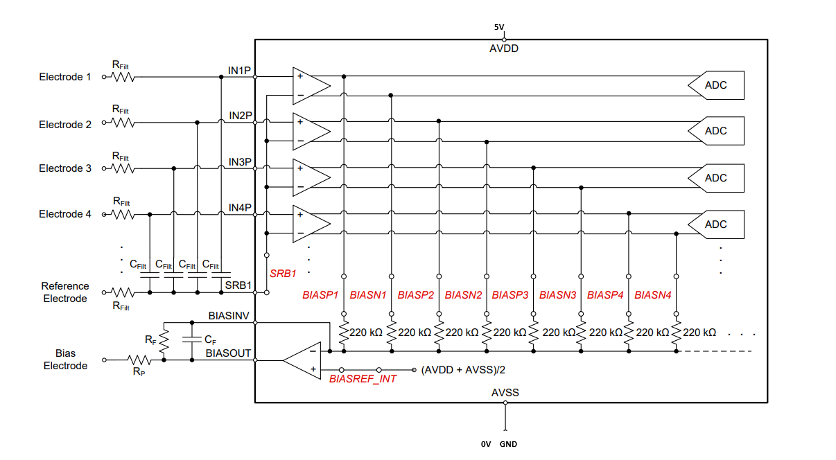
  • Input Configuration:

    • 4 Signal Inputs

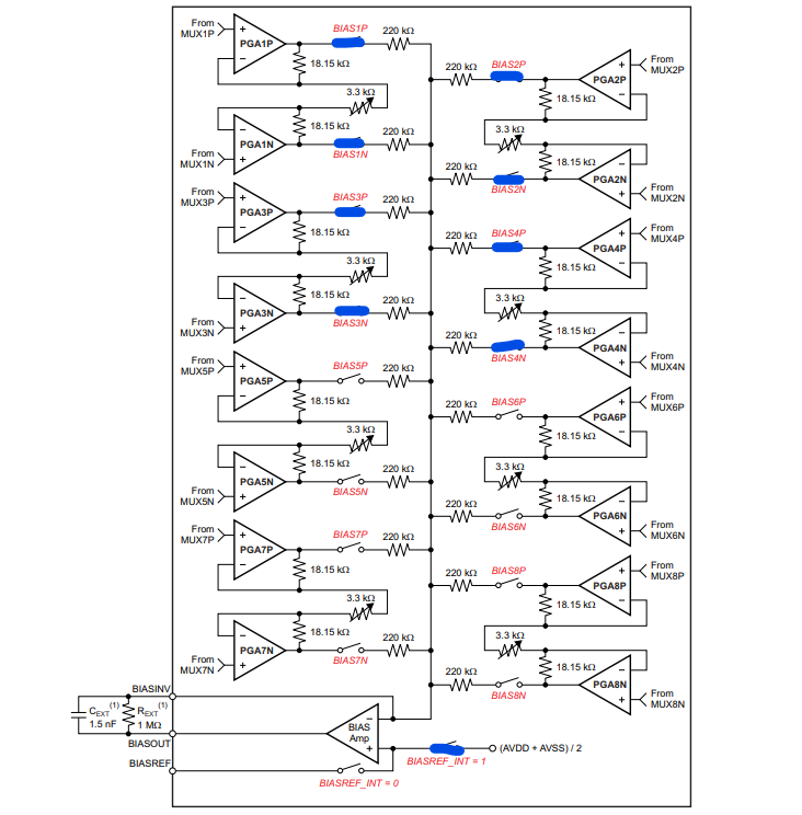
    • 1 Bias Electrode

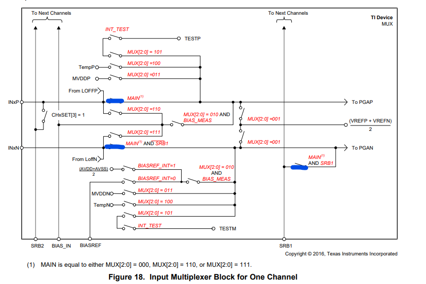
    • 1 Reference Electrode (Using SRB1 for referential configuration)

Configuration Settings:

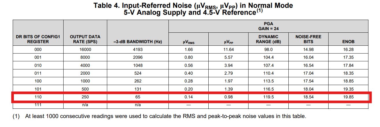
  • Gain: 24

  • Data Rate:: 250 SPS

  • Reference: SRB1 enabled (Referential montage)

  • Register Settings: (Please see the attached screenshots of my register map).

The Issue: Based on the ADS1299 datasheet, at Gain=24, I am expecting a much higher dynamic range and approximately 18.5 bits of noise-free resolution.

However, in my current tests, I am effectively getting only 11 bits of data, with approximately 8 bits being noise-free. The noise floor is significantly higher than expected.

Attachments:

  1. Register Map / Configuration: image.pngeb07648e-19f8-4bfa-a14f-756d378052da.pngim1.pngimage.png

My Questions:


  1. Can you help me identify the source of the problem I'm experiencing?
  2. Could you review my register settings (attached) to ensure I haven't missed a critical configuration for the SRB1/Bias setup?

Any advice on troubleshooting this noise floor issue would be greatly appreciated.

Best regards,


  • Hello Atıf,

    Thank you for your interest in our ADS1299. Noise performance shortcomings can be difficult to troubleshoot. The datasheet specifications pertain only to the IC - any additional noise must be coupling through the rest of the system (i.e. power supplies, input signal source, PCB traces and parasitic coupling, power line interference, etc.). You will need investigate this closely in your own setup to identify the root cause and the nature of the noise before knowing what can be done to remove it from your results. I suggest starting with an internal input-short condition, followed by an external short condition at the electrodes. You may view this data in the time/frequency/histogram formats to understand the type of noise that is coupling.

    Regards,

    Ryan

  • Hello Ryan,

    Thanks for the quick response. What we really try to find out is the ideal gain ADS1299 provides for the EEG signals. Considering a 10-microvolt EEG signal, what would be the ideal gain when the abovementioned configuration is in place? Is it 240 microvolts? 

  • Hi Atif - yes, the gain for all differential signals would be 24V/V in this configuration within the passband of the PGA.

    Regards,

    Ryan