This thread has been locked.

If you have a related question, please click the "Ask a related question" button in the top right corner. The newly created question will be automatically linked to this question.

AFE4404: Hardware-Power-Down

Part Number: AFE4404

Hello,
 
What are the mandatory steps to put the IC into Hardware-Power-Down mode?
 
Here are the steps expected to do the job:
0. Start MCU
1. 200ms sleep (Let the AFE's power supplies settle)
2. Configure RESETZ pin as output(open-drain, RESETZ line has external pull-up 4k7 resistor)
3. Put RESETZ low for 40us (25-50us range).
4. Put RESETZ high for 10ms.
5. Put RESETZ low for 500us (>200us range).
6. Put RESETZ high.

At this point, I expect the device to enter HWPDN mode.
However, this is not happening. The IC still consumes approximately 500µA, and I am still able to read/write registers over I2C after completing these steps.
I verified the RESETZ line continuity by confirming that I2C communication fails when RESETZ is held low, which it does.
Software-Power-Down works as expected, the current consumption drops to ~40uA.

I was able to reproduce that on my custom HW and Heart Rate 5 Click from Microe.
I haven't tested this on AFE4404 EVM.
 
I even tried to mimic the exact same code as implemented in AFE4404EVM_FW project.
 
void AFE4404_RESETZ_Init (void);
void AFE4404_Enable_HWPDN (void);
void AFE4404_Disable_HWPDN (void);
void AFE4404_Trigger_HWReset (void);
 
but still with no success.
 
  • Could you share the current consumption graphs while putting the IC into Hardware-Power-Down mode?
  • Is there something specific that must be done before that?
  • Is Hardware-Power-Down mode working as expected on AFE4404 EVM?
  • What HW issue can block entering the HWPDN?

Here is the HW schematic.

RST, CLK, MODE, INT, SCL, SDA lines are directly connected with MCU(nRF52840)
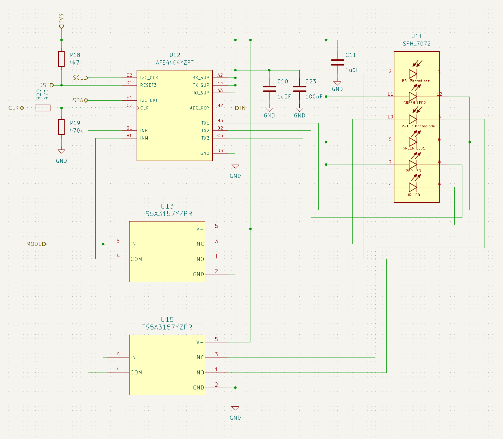
image.png

  • Hello Pawel,

    To put the AFE4404 in hardware power-down mode, the RESETZ pin needs to be held low. Pulling the RESETZ pin back high (as in Step #6 above) will end hardware power-down mode.

    Regards,
    Payton

  • Hi Payton,

    Thanks for your quick response. Isn't the word "pulse" in the datasheet confusing then?

    If the RESETZ line must be held low, then for low-power applications it is recommended to use huge external pull-up resistor? The AFE4404 EVM has a 10kΩ external pull-up, so if the line must be kept low, the current flowing through it will be approximately 330µA with a 3.3V IO_SUP. 

    I have tried your suggestion and removed Step #6 (no external pull-up, push-pull configuration), but unfortunately it didn't help. The current consumption is still much greater than expected. Do you have any other ideas about what the issue could be?

    Regards,

    Pawel

  • Hi Pawel,

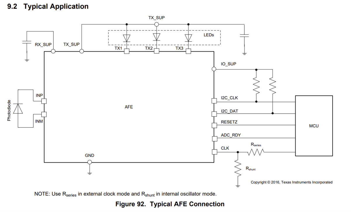
    In general, RESETZ is tied to the MCU, as seen in the "Typical Application" below.

    Are you using an internal or external clock? If you are using an external clock, is that clock shut off (either tri-stated or driven to 0) when attempting to enter Hardware PWDN more?

    Regards,

    Payton

  • Hi Payton,

    Regarding the typical application circuit: What is the internal design of the RESETZ pin? Is it internally pulled high or low?

    I'm working on minimal code to put the IC into Hardware-Power-Down mode, which means I don't configure any registers. Based on my understanding of the datasheet, this should be achievable using only the RESETZ line. However, we can assume I'm using an external clock since that's the default value of the OSC_ENABLE field. The CLK pin is in a Hi-Z (high-impedance, non-configured) state on the MCU side.

    Regards,
    Pawel

  • Hello Pawel,

    In both Hardware PWDN and software PDNAFE mode, the clock pin can either be driven to 0 or tri-stated. Since the CLK pin is currently unconfigured in Hi-Z, this meets the criteria for the clock pin in hardware PWDN mode.

    "When in power-down mode (PWDN and PDNAFE) the CLK pin must be shut off (tri-stated or driven to zero), if externally driven.

    If this is the case, then you should be able to enter hardware PWDN mode by driving the reset pin low for at least 200μs.

    • Do you have the ability to test this on the AFE4404EVM?
    • Can you check the connectivity between RESETZ on the AFE4404 and the MCU control for RESETZ?
    • How are you verifying that the device is/is not in hardware PWDN mode?
    • How long are you holding the line low before checking that the device is in hardware PWDN mode?

    Regards,

    Payton

  • Hi Payton,

    • Yes, I can test this on AFE4404EVM but it will require some additional effort and if possible I would like to postpone that step until necessary.
    • I cannot test it end to end, due to their SMT packages but when I hold the RESETZ low then dummy I2C write to register fails, when it is high then I2C works, so I believe there is no issue here.
    • I have Nordic Power Profiler kit connected to the hardware and by checking the current consumption I determine whether PWDN mode is working or not. When using PDNAFE (Software-Power-Down) the current consumption is at level X and when trying to utilize the Hardware-Power-Down I constantly see the current-consumption at the level of 10*X which shows me that it is not working as expected.
    • I can hold it forever. I just observe the current-consumption level. Is there any other method to check if device is in the Hardware PWDN? 

    Could you provide a simple guideline how each of the pins are expected to be configured when in hardware PWDN? 
    I just got a feeling that improper IO configuration causes some unwanted current flow.

    Regards,

    Pawel

  • Hi Pawel,

    Let me look into this and get back to you early next week.

    Regards,

    Payton

  • Hi Pawel,

    Thank you for your patience.

    • What is the exact current measurement you are reading in hardware power-down mode?
    • Are you driving any inputs to the IO pins during hardware power-down mode? Doing so may be causing the currents you are reading.
    • Can you measure the voltage at each of the pins you are reading during hardware power-down mode?

    Regards,

    Payton

  • Hi Payton,

    • That might be misleading as there are multiple other components consuming power on my +3.3V bus. Maybe providing the difference in current in between Software-Power-Down and Hardware-Power-Down will be more beneficial?
    • Only RESETZ IO pin is driven low. Others are Hi-Z
    • Not on my custom board, but maybe for the sake of simplification, I will create a sample demo utilizing Heart Rate 5 Click from Microe.

    Regards,

    Pawel

  • Hi Pawel,

    Thank you -- let me know when you're able to measure the pin voltages.

    Is it possible to isolate the AFE4404 on the power line and measure current consumption? If not, I would still like to know the raw current measurements you are reading in both Hardware and Software PWDN mode.

    Regards,

    Payton

  • Hi Payton,

    I will get back to you after isolating the AFE4404 with all of the details.

    Regards,

    Pawel

  • Hi Payton, 

    I'm back with good news only.

    I managed to properly isolate the AFE power rail and re-measure the current consumption. It turned out that my previous investigation was not 100% correct. I believe I initially measured the current incorrectly after removing the external RESETZ pull-up, which led me to the wrong conclusions.

    Current consumption measurements (VCC = 3.0 V):

    • Software Power-Down (PDNAFE): ~34 µA

    • Hardware Power-Down: ~31 nA

    Toggling the RESETZ pin causes the current consumption to change from ~31 nA (Hardware Power-Down) to ~432 µA (no power-down mode applied).

    To be honest, the current consumption in Hardware Power-Down is surprisingly low. However, the RESETZ toggling test clearly confirms that there is no issue with the current measurement setup.

    So far, I have two brief conclusions:

    1. RESETZ must be held low to enter Hardware Power-Down.

    2. For low-power hardware designs, the RESETZ line should not use an external pull-up resistor, as it introduces unnecessary static current.

    My final question concerns the internal implementation of the RESETZ pin in the AFE4404.

    How is this input configured internally?
    Does the RESETZ pin need to be actively driven high and low by the MCU, or are simple pull-up / pull-down configurations on the MCU side sufficient (i.e., leaving the pin high-Z with an internal pull-up or pull-down enabled)?

    Thank you in advance for your clarification.

    Regards,
    Pawel

  • Hello Pawel,

    I'm glad that you were able to figure out what was going on.

    Pull-up and pull-down configurations on the MCU side are sufficient to drive the RESETZ pin high or low.

    Regards,

    Payton