ADS1120: OHM sensor reading

Part Number: ADS1120
Other Parts Discussed in Thread: ADS112S14

Hello,

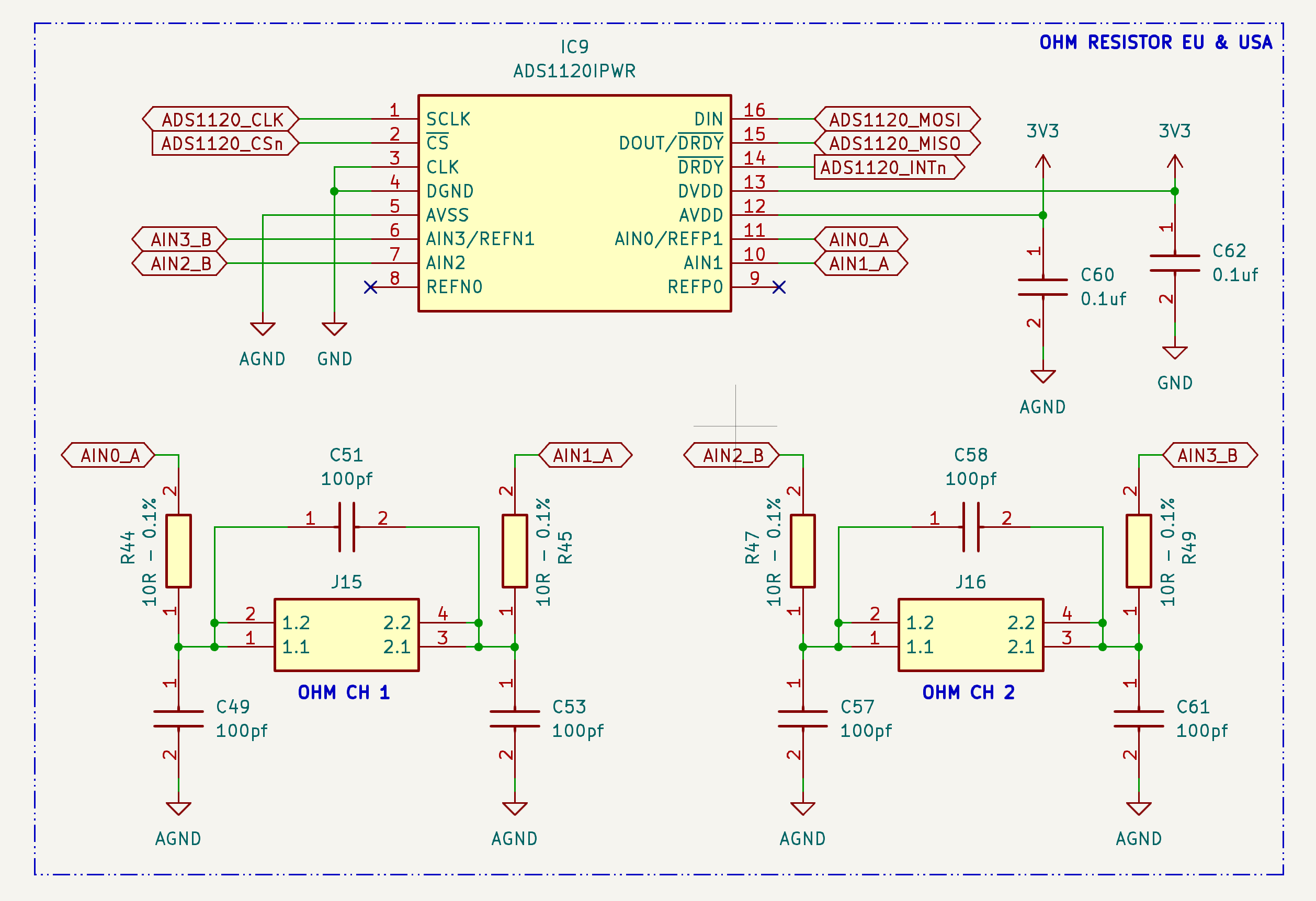
We are encountering the following problem with the ADS1120IPWR model: we need to read both the EU (10-180) and US (240-33) ohm sensors. As shown in the circuit diagram below, we use channels AIN2 and AIN3 for reading. AIN2 sends approximately 1.5 mAh and the reading is performed with channel AIN3. The connected sensor is correctly read with approximately 9k values, while if I connect the same sensor to channels AIN0 and AIN1, with AIN0 sending approximately 1.5 mAh and AIN1 reading the sensor, the value is almost zero with approximately 20 values. BCS is off in both configurations. AIN2 and AIN3 work, while AIN0 and AIN1 don't when using this circuit. Could you kindly help us solve this problem?

 Screenshot 2026-02-16 at 11.31.45.pngThank you very much

  • Hi Alex, 

    Welcome to the E2E forum and thank you for your interest in out Precision ADCs!

    Can you send the register settings for the two configurations?

    Can you send a screen capture of the waveforms or output data for the two configurations, showing the variation between the two outputs?

    Have you seen this behavior across multiple devices or just one?

    A note on your schematic is the common mode capacitors should be a full decade smaller than the differential capacitors. So in your case C49, C53, C57, and C61 should be 10x smaller than C51 and C58 respectively. (10pf)

    Regards, 

    Andrew

  • Hello,
    Thank you for your kind reply. we solved the initial issue. It turns out that we had a mistake in SPI communication, so we were unknowingly closing the PSW switch, bringing AIN3 to GND, which is what made the AIN2-AIN3 measurement work. Wiring AIN0 to GND and AIN3 to GND in our circuit made it work for both channels (muxer set to AIN1-AIN0 and AIN2-AIN3 respectively), with PSW now disabled.

    Looking around the E2E forum we also realized we need a Rref reference resistance between REFP0 and REFN0 to be able to interpret the values read. So now we added a 470ohm resistance between REFP0 and REFN0, with REFN0 also wired to GND.
    Finally, we noticed that the result codes we were getting based on this added Rref were 6-9ohm off of the expected values, and replacing the 10ohm balancing resistances on AIN0, AIN1, AIN2 and AIN3 with 0ohm ones removed this offset and gave results very close to the expected ones (within 1-3ohm).

    Here is a recap of the final working situation for reference (in case it can be useful to someone else, or if we are still doing something wrong despite the apparently good results):

    We are measuring 2 fuel tank depth resistance-based sensors, one is 10-180ohm and the other is 240-33ohm, voltmeter shows the actual ohm values are as advertised. They are connected to AIN2-AIN3 and AIN1-AIN0 respectively, with AIN3 and AIN0 wired to GND as well. We have a 470ohm Rref between REFP0 and REFN0 with REFN0 also wired to GND.

    Code-wise, we start by resetting the sensor to default values, then change the IDAC current to 500uA and enable IDAC1 on REFP0. At this point we set VREF to REFP0-REFN0, then carry out a calibration by setting MUX to (V(REFPx) – V(REFNx)) / 4, taking 10 measurements and summing them, dividing by 32767 (2^15, adc scale), multiplying by 2048 (the internal Vref) and multiplying again by 4 (as the measurement is / 4), finally dividing by 10 to take an average. This calibration results in a REFP0-REFN0 Vref of 232mV, which is very consistent across different runs and consistent with voltmeter measurement across Rref. After this we begin the actual measurements, by enabling IDAC2 on AIN1, setting MUX to AIN1-AIN0, and reading a measurement code. Then doing the same for the other channel: enabling IDAC2 on AIN2, setting MUX to AIN2-AIN3, and reading a measurement code.

    This gives very consistent measurement codes. On the first sensor we get 631 (0x0277) low (should be 10ohm) and 12513 (0x30E1) high (should be 180ohm). On the second sensor we get 16697 (0x4139) low (should be 240ohm) and 2222 (0x08AE) high (should be 33ohm).

    Following a similar conversion as the calibration: divide by 32767 (2^15, adc scale) and multiplying by 232 (the calibrated Vref from Rref), this gives: 4.5 - 88.6 for the 10-180ohm sensor and 118.2 - 15.7 for the 240-33ohm sensor. These results are very close to half the expected result (multiplying by 2 would give 9.0 - 177.2 for the 10-180ohm sensor and 236.4 - 31.4 for the 240-33ohm sensor).

    We also tried with a different REFP0-REFN0 Rref of 330ohm, this gave higher result codes but a lower Vref calibration of 164.5, so the resulting converted values were the same.
    It seems the converted results are half the expected ones due to the 500uA we're using for IDAC. Using 1000uA gives twice the Vref on Rref (465mV for 470ohm Rref), and thus twice the converted results as listed before, which is close to the expected results and satisfactory for our use case.
  • Hi Alex, 

    Glad you were able to solve the initial problem. Thank you for the update and the detailed solution.

    From your description your methodology seems sound however the reference voltage that you have outlined does fall outside the reference input voltage specification in the datasheet. Now this can work as you highlighted above but might not meet exact datasheet specifications. I would suggest increasing the Rref to meet this specification. 

    I understand the system is working as you expect, here are two additional options that you could consider for your design:

    1) Both the EU and US sensors were both always installed:

    You could do a high-side reference with the two sensors in series. This could eliminate the need for the reference calibration since the Rref will be a known value with 0.1% variance. This would be similar to an example from A Basic Guide to RTD Measurements with the IDAC output instead running through the REFP0 pin and and the two resistor measurements occurring over the same pins your are using now. 

    2) Either the EU sensor or the US sensor are installed:

    A low-side reference with the two sensors in parallel could work with our new ADS112S14, which will release soon the datasheet is attached to the ADS122S14. With the ADS112S14 additional pins you could route the IDAC to the parallel sensors and measure the known Rref through a low-side reference. Similar to the example of measuring parallel 2-wire RTDs in A Basic Guide to RTD Measurements except with only two measurements. 

    Regards, 

    Andrew