This thread has been locked.

If you have a related question, please click the "Ask a related question" button in the top right corner. The newly created question will be automatically linked to this question.

AMC60704: ADC averaging function

Part Number: AMC60704

Hi team,

My customer has questions regarding ADC averaging function. Could you please kindly help me answer questions below?

  1. How long does it take to complete the averagings?
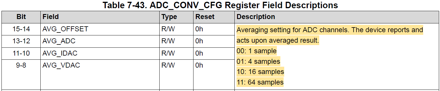
image.png

2. In auto mode, the user can obtain the 4 samples averaged result every time by reading the DATA registers if the AVG_ADC bit is 01. Is my understanding correct?

3. What is the difference between CONV_OFFSET bit and CONV_ADC bit?
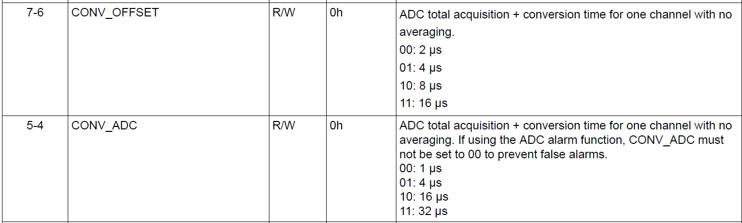
image.png

4. If CONV_ADC = 00 and AVG_ADC = 01, The period which the user can obtain the averaged result every time is 4us since the the number of samples for the averaging is 4 samples. Is my understanding correct?

Best regards,

Shunsuke Yamamoto

  • Hi Yamamoto-san,

    1) One average is equal to an additional conversion. So, if you have a conversion rate of 2us, 1 sample = 2us, 4 samples = 8us, 16 samples = 32us, etc.

    2) You are correct.

    3) The "CONV_Offset" register lets you configure the conversion time specifically for the "Offset" measurements. The device has an "ADC Offset Calibration" measurement that it uses to improve the VDAC current monitoring accuracy. There are no registers you can read back for this measurement, I think.

    The "CONV_ADC" modifies the conversion rate for the ADC1, 2, 3, and 4 pins.

    4) Correct. Note that the conversion rate is also dependent on the CCS (Custom Channel Sequence).  For example, if you have "VDAC1" and "VDAC2" as the only 2 options in your sequence, and both take 4us to average and measure, you will get an update on VDAC1 every 8us. 

    Thanks,
    Erin

  • Hi Erin-san,

    Thank you for the clear explanation. It helps us accelerate customer's evaluation! I received additional questions regarding ADC function. Could you please kindly help me answer them?

    5. What is the function of AVG_OFFSET? How does it work?

    6. What is the performance difference between conversion time? My customer suspects that the conversion time affects the resolution and the bit rate of ADC.

    Best regards,

    Shunsuke Yamamoto

  • Hi Yamamoto-san,

    5) The "Offset" registers refer to the ADC calibration function. The customer cannot read the output of these registers, but they help with the ADC accuracy.

    6) We unfortunately do not have a good table of information for how the conversion rate affects the result, but in general, an increase in conversion rate will increase ADC accuracy. For example, a 32us conversion rate will be more accurate than a 1us conversion rate.

    Thanks,
    Erin

  • Hi Erin-san,

    Thank you for the answers.

    5) The "Offset" registers refer to the ADC calibration function. The customer cannot read the output of these registers, but they help with the ADC accuracy.

    ->It is good to know Offset registers are ADC calibration function. Could you please kindly explain the details how the ADC accuracy is improved by Offset registers?

    6) We unfortunately do not have a good table of information for how the conversion rate affects the result, but in general, an increase in conversion rate will increase ADC accuracy. For example, a 32us conversion rate will be more accurate than a 1us conversion rate.

    ->I understood that the conversion rate affects the output of ADC accuracy. If you have measurement result of input signal by ADC with 4us conversion rate and 32us conversion rate, it is helpful if you could share it with me.

    Best regards,

    Shunsuke Yamamoto

  • Hi Yamamoto-san,

    Here's some example measurements I took on bench:

    I applied 3.3V to ADC1. A precision multimeter measured 3.30004V. I used 1 sample with gain = VREF x 2.

    Conversion Rate ADC Min ADC Max Vmeasured Min Vmeasured Max % Error
    1us AC3 AC8 3.363037109 3.369140625 2.0026%
    32us A8F A92 3.299560547 3.303222656 0.0421%

    As this shows, the higher conversion rate is significantly more accurate.

    As for the offset information: The datasheet doesn't really specify, but it seems like the offset calibration helps the VDAC IMON accuracy. 

    Thanks,
    Erin

  • Hi Erin-san,

    Thank you for the reply and the comparison table. Regarding ADC conversion rate, I understood that 32us of conversion rate has better accuracy.

    Regarding AVG_OFFSET register, could you please also create the comparison table in case of 1 sample, 4 samples and 64 samples like you measured the conversion rate? It is easy for my customer to understand the performance of AVG_OFFSET register.

    Best regards,

    Shunsuke Yamamoto

  • Hi Yamamoto-san,

    I will be able to check this tomorrow. Thank you for your patience.

    Thanks,
    Erin

  • Hi Erin-san,

    Thank you for the continuous support. We are close to win the socket of AMC60704...

    Best regards,

    Shunsuke Yamamoto

  • Hi Yamamoto-san,

    Here's some information about the OFFSET register:

    When the device starts up, it has a default "CCS" sequence. This is the conversion sequence the ADC goes through. By default, the ADC OFFSET channels (ADC CORE OFFSET, VDAC 1/2 CURRENT OFFSET, and VDAC 3/4 CURRENT OFFSET) go first in the sequence. These channels are used to calibrate the offset of ADC and VDAC IMON. Here is an example I ran on bench:

    -I reset the device
    -I removed the ADC OFFSET channels from the CCS.
    -I enabled the VDACs and set them to 0V, no load. By default, this means the ADC should read ~0mA.
    -Triggered the ADC. The following table shows the current values on each VDAC measured by the ADC.

    VDAC1 VDAC2 VDAC3 VDAC4
    No Calibration 762.9uA 724.8uA 419.6uA 343.3uA

    -I enabled the ADC OFFSET channels in the CCS
    -Triggered the ADC. Now, the currents are closer to the correct 0mA! This is performed with the default conversion/samples.

    VDAC1 VDAC2 VDAC3 VDAC4
    Calibration 38.1uA 0uA 38.1uA 38.1uA

    Another example. This time, I loaded the VDAC output. Here are the results:

    VDAC1
    Multimeter 10.919mA
    No Calibration 11.4mA
    Calibration 10.7mA

    You can see in this case, the VDAC had an offset of around 500uA, which the calibration removed. 

    At these low currents, I did not see a large difference between samples or conversion rate. At very high or very low currents/voltages the customer might benefit from modifying the conversion and sample rates, but on bench I did not see a noticeable difference.

    In addition, I went back and looked at my ADC sample/conversion rate data. It seems like I may have messed something up in the previous data, because the data I got today was much better! Here's how it breaks down. Conversion rate increases the accuracy of the ADC reading, and sample rate increases the precision of the data (less oscillations).

    Conversion Rate Sample Rate ADC1 (3.3V input)
    1us 1 3.28735V Oscillation (~5LSB)
    1us 64 3.29102V No oscillation
    32us 1 3.29102V Oscillation (~4LSB)
    32us 64 3.29224V No oscillation

    Thanks,
    Erin