Part Number: ADS8355
This thread has been locked.
If you have a related question, please click the "Ask a related question" button in the top right corner. The newly created question will be automatically linked to this question.
Part Number: ADS8355
Hello Ayyappan,
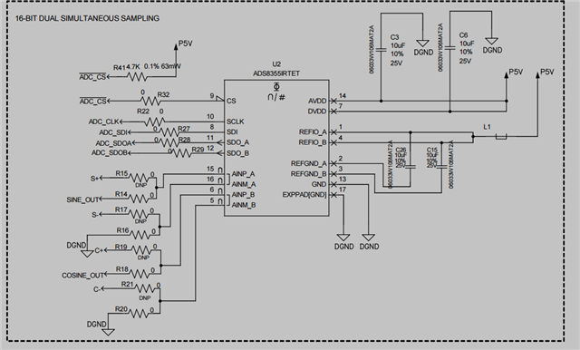
Would you be able to share a schematic of the ADS8355 in your system?
Is the ADS8355 configured with the internal reference or does it have an external reference? If the external, what is the external reference source?
Would it be possible to measure the voltage at REFIO at a 25°C temp as well as the -40°C?
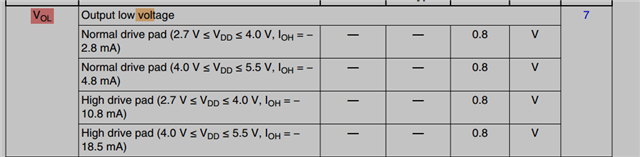
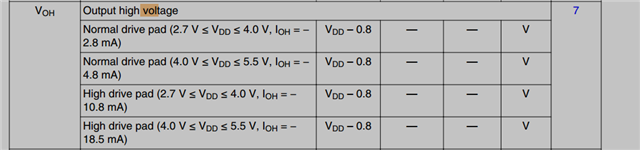
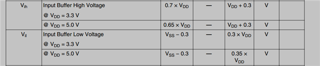
Would you also be able to share the DVDD set voltage, the controller set voltage, its VOH/L an VIH/L limits? and if possible a screen shot of the digital communication between them?
Best regards,
Yolanda
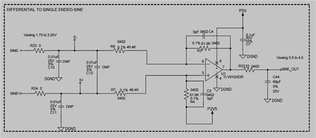
I’ve attached a screenshot of the schematic showing the OP‑amp stage, the ADC (ADS8355) interface, and the communication lines to the controller.
In our design, the ADS8355 is configured to use an external 5 V reference, which is derived from a switching regulator. This same 5 V rail is shared across all active components in the circuit.
I’ve also attached the controller’s VIH/VIL and VOH/VOL specifications for your reference.
In the schematic, the outputs of the OP‑amp are routed to the ADC inputs 33E, and each of the sine and cosine channels includes a 1 nF capacitor at the ADC input.


Hello Ayyappan,
Thank you for sharing all of the schematics and the digital supply information.
Do you have any specifications on what the accuracy and noise of the switching regulator used for the 5V supply?
Is the P2V5 for the TLV offset derived from the same P5V as well?
Because the ADC performance is highly dependent on the reference, direct sharing with the supplies is not always recommended. Ideally we recommend adding a driver for ideal performance, if possible an RC, or at minimum some way to disconnect from supply noise or switching, which its great that there is an inductor. A 5V reference is also what we saw the device preform the best with, so another plus.
Would it be possible to perform a test at -40C without the inductor an the internal reference to see if the large offset improves?
Thank you as well for sharing the VxH/L from the controller, this looks great as well. I just wanted to confirm.
Best regards,
Yolanda
Hi Yolanda
We are using a MAX17502 switching regulator to step down 28 V to 5 V, and the op-amp reference is generated from a REF3425 (REF3425TIDBVR).
Would you recommend testing the design with an isolating inductor and enabling the ADC’s internal reference? Additionally, is it possible to configure the ADC to use an internal 5 V reference? Because my analog output voltage from Op-amp vary from 0.5 to 4.5 Volts.
Regards
Ayyappan A
Hello Ayyappan,
As a form of debugging to see if the error is being caused by the 5V supply, I was wondering if you would be able to test the offset without the inductor (L1), and with the internal reference.
The ADS8355 has a "2xVref" range that should enable the input range to be 0V to 5V, by setting RANGE_SEL = 1. Would this be possible?
Or using the the REF3425 and the 2xVref range instead of the 5V would also help
Could you confirm if the L1 is an inductor or a ferrite bead?
Ideally each REFIO should have their own reference path, with a buffer, but having a ferrite bead at least helps a bit.
Best regards,
Yolanda