This thread has been locked.

If you have a related question, please click the "Ask a related question" button in the top right corner. The newly created question will be automatically linked to this question.

ADS7128: schematic review request.

Part Number: ADS7128
Other Parts Discussed in Thread: CD74HC4067

Hello TI team,

I am using CD74HC4067 together with ADS7128 to measure multiple analog voltages by multiplexing the signals into one ADC channel.

I have attached the schematic and would appreciate your help in reviewing whether this circuit configuration is suitable for analog voltage measurement.
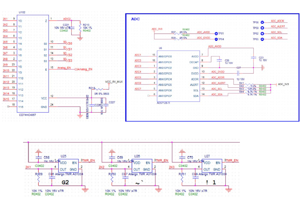
 

image.png


When connecting the MUX output directly to the ADC input, are there any recommended design considerations (such as adding an RC filter, buffer amplifier, or source impedance limitations)?

Thank you for your support.

Best regards,
Tom

  • Part Number: CD74HC4067

    Hello TI team,

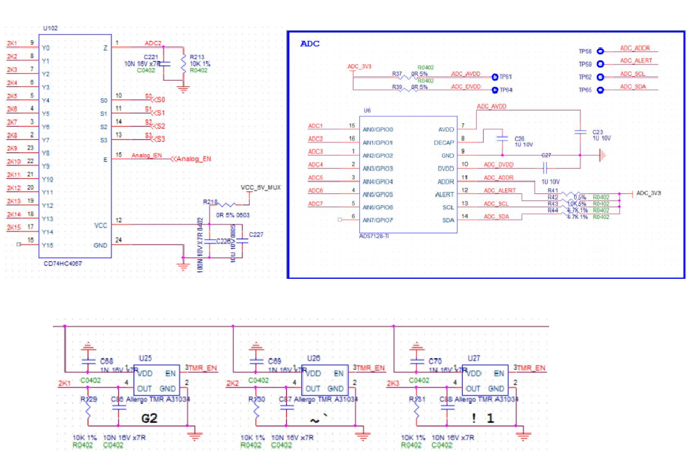
    I am using CD74HC4067 together with ADS7128 to measure multiple analog voltages by multiplexing the signals into one ADC channel.

    I have attached the schematic and would appreciate your help in reviewing whether this circuit configuration is suitable for analog voltage measurement.


    image.png


    When connecting the MUX output directly to the ADC input, are there any recommended design considerations (such as adding an RC filter, buffer amplifier, or source impedance limitations)?

    Thank you for your support.

    Best regards,
    Tom
  • Hi Tom,

    I'm not seeing any specific voltages for the input or select pins, but as long as they are within datasheet spec, I don't see any concerns on the mux end. If this is a higher frequency application, I would recommend terminating the unused pin (Y15) to ground (typically through a 50ohm resistor, but dependent on the termination of the system).

    I am reassigning to the ADC team for comment on the ADC section of the schematic.

    Best,
    Katy

  • Hi Tom,

    I've merged the mux and ADC threads together.

    It is usually recommended for each mux input to have its own RC filter. This is to help maintain the input voltage stable, as when the mux switches, the ADC input can see a large transient. Having a filter for each mux input helps supply the ADC sampling capacitor with charge rapidly, and reduces the occurrence of settling errors.

    Can I ask the sampling rate requirements, and what kind of inputs will be supplied to the ADC? This is to help determine adequate RC values.

    Regards,
    Joel

  • Hi Joel,

    Thanks for the quick response.

    Regarding the specifications, the Mux will switch every 4us, and the MCU will poll the ADC at a frequency of 8Khz. The input signals is random voltage levels.

    We look forward to your recommendations on the adequate RC values based on these parameters. Thanks!

    Best regards,

    Tom

  • Hi Tom,

    Sorry, for the late response, as I was sick last week.

    Values of 100 ohm and 100nF would be a good start. This settles to 12-bit accuracy in less than 20us given a 3.3V step input. Given that there is 125us between the ADC samples, this is sufficient.

    Regards,
    Joel