ADS52J90: Simultaneous sampling with multiple ADCs

Part Number: ADS52J90

Dear Technical Support Team,

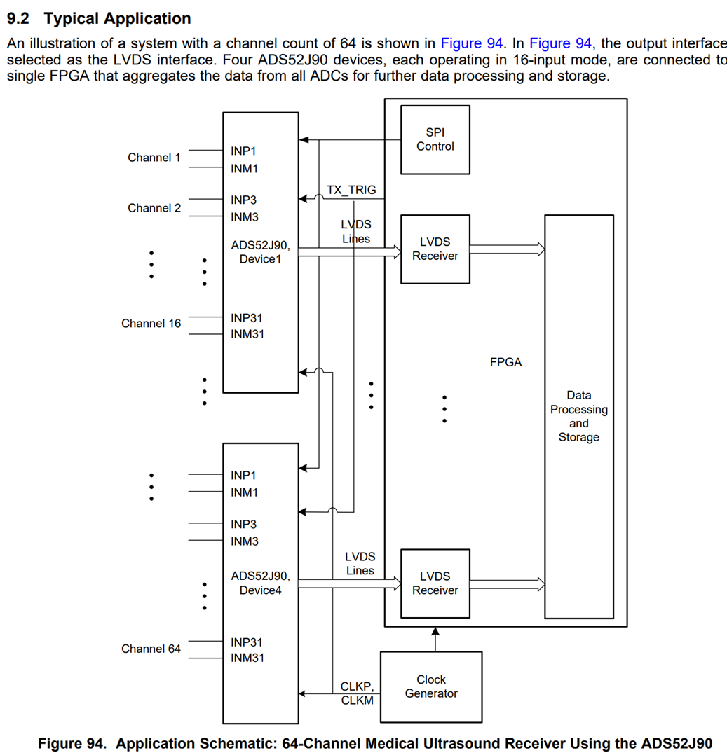
I aim to do simultaneous sampling with multiple ADCs(sampling timiming difference between channels within 1ns)

For example , datasheet has four ADS52J90(16ch) for 64ch analog input.

Q1

Can four ADS52J90 for 64ch analog input sample simultaneously?

Q2

For acheving sampling timiming difference between channels within 1ns, does the skew of  four sampling clocks(CLKM/N) and four trigger signals also need to be within 1 ns?

Q3

Are there any application notes or reference designs for applications using multiple ADS52J90s, such as the one described here?

image.png

Best Regards,

ttd

  • Hi,

    1. Multiple parallel devices can be synchronized by giving synchronization pulse on TX_TRIG pin. Please see the datasheet section 8.3.4 Device Synchronization Using TX_TRIG. This allows simultaneous sampling of all 64 channels 

    2. Yes. The skew of  four sampling clocks(CLKM/N) needs to be within 1 ns. Regarding the TX_TRIG skew, it has to meet set up and hold time requirements with respect to system clock. Timing requirement of TX_TRIG with respect to system clock is mentioned in the datasheet. TX_TRIG signal eventually gets latched at the rising edge of system clock and minimum delay of latched TX_TRIG is 0.5ns. 

    3. Application note for multiple ADCs is not available. Only datasheet has the application details. 

  • Hi,

    Tnank you for your reply.

    I have additaion questions for 1,2 and 4.

    1.

    8.3.4 Device Synchronization Using TX_TRIG seems to describe only 32-Input Mode and 8-Input Mode. In my case, I'd like to use 16-Input Mode.

    Do you have any guidence and timing chart for 16-Input Mode?

    Does "System Clock" mean sampling clocks(CLKM/N) from external?

    My taget sampling rate is 10MSPS

    Figure 60. Odd- and Even-Channel Sampling Instant Definition Mechanism in 32-Input Mode with the TX_TRIG Signal

    Figure 61. Conversion Clock Deriving Mechanism from Division of the Sampling Clock in 8-Input Mode

    2.

    I understand your advices.

    By the way, is it possible to add delay to the internal clock generator?

    Please let me know if there is a feature that allows for fine-tuning in case of skew in the input clocks of the four ADCs.

    3.

    OK, I refer to datahsheet.

    4.

    What is the sampling timing error for the 16 internal ADCs (xx ns or xx ps)?

    I believe the tap (aperture delay) is 1.6 ns (typ) between the externally supplied system clock, fS, and the conversion clock, fC, supplied to the 16 ADCs by the clock generator. Since the clock is supplied to each ADC with a delay of tAP = 1.6 ns (typ), is my understanding correct that the sampling timing error is extremely small between 16 internal ADCs?

    δtAP (aperture delay variation from device to device) is ±0.5 ns. For example, if Device A is +0.5 ns and Device B is -0.5 ns, would the worst-case scenario result in a maximum sampling timing error of 1 ns between the two devices?
    In the application example with four devices, would the maximum sampling timing error still be 1 ns?

    Addtional Information.

    My target configuration is simultaneous sampling of all 256 channels with 16 ADS52J90s (16-Input mode/12bit/10MSPS) 

    Best Regards,

    ttd

  • Hi,

    1. In terms of TX_TRIG delay, it will be similar to Figure 60 Odd- and Even-Channel Sampling Instant Definition Mechanism in 32-Input Mode with the TX_TRIG. For the data sampling instant please refer to Figure 57, 58 and 59 of the datasheet. Figure 58 describes the data sampling instants for 16-input mode.

    System clock is the external clock applied at CLKM/P pins

    2. There is no feature to fine-tune the skew in the input clocks of the four ADCs

    3. Yes, sampling timing error is less than 0.1ns between 16 internal ADCs. 

    Would the worst-case scenario result in a maximum sampling timing error of 1 ns between the two devices?  ---- Yes, it could be possible

    Across devices, the typical value of sampling timing error is 1ns. In system which has 4 devices, the typical variation across all devices would be 1ns.

  • Hi,

    Thank you for your reply.

    Is there a way to measure the sampling timing error δtAP (aperture delay variation between devices) between two devices on an actual circuit board?

    If I input the same data, such as a sine wave, into 256 channels, perform analog-to-digital conversion, and then systematically calibrate the system by comparing several cycles of data using an FPGA, can I align the timing within 1 ns?

    Best Regards,

    ttd