This thread has been locked.

If you have a related question, please click the "Ask a related question" button in the top right corner. The newly created question will be automatically linked to this question.

AMC131M03: AMC131M03DFMR- Main clock input.

Part Number: AMC131M03
Other Parts Discussed in Thread: CDC6C

Hi Team,

I am Anees PK from RIODLogic India. We are planning to use the AMC131M03 isolated ADC for measuring oil pipeline voltages with respect to reference GND in our project.

In my requirement, I only need a data rate of around 1000 SPS with 14- or 16-bit resolution.

While referring to the datasheet and evaluation board, I understand that a main clock input is required on pin 17 of the IC. As per the evaluation board, this clock is generated using a VCO/oscillator IC (Y1 on the EVK board: SIT8924BA-22-33E-8.192000G). However, this part is currently not available, so please suggest a suitable alternative.

Also, please confirm whether a precise 8.192 MHz or 4.096 MHz clock is required. Alternatively, can I generate a clock signal (e.g., 1 MHz or 4 MHz) from the microcontroller using PWM or a timer (0–3.3V clock pulse)?

Additionally, will there be any issues if the clock varies slightly (e.g., 1 MHz to 1.05 MHz), or is strict precision (such as exactly 4.096 MHz or 8.192 MHz) required?
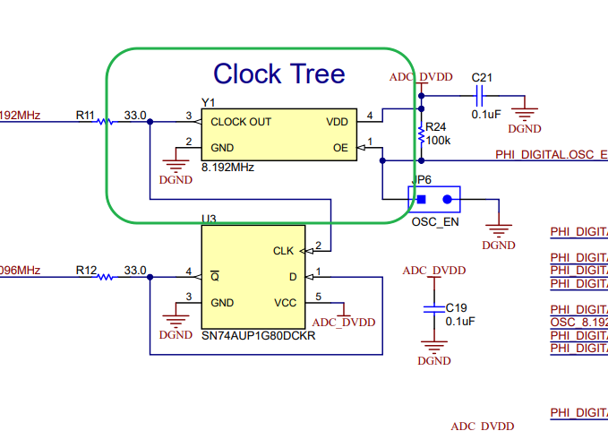
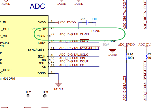
 

image.png
image.png
Regards
Anees PK

  • Hi Anees,

    While referring to the datasheet and evaluation board, I understand that a main clock input is required on pin 17 of the IC. As per the evaluation board, this clock is generated using a VCO/oscillator IC (Y1 on the EVK board: SIT8924BA-22-33E-8.192000G). However, this part is currently not available, so please suggest a suitable alternative.

    You can take a look at the following parts as an alternative source for the clock: CDC6C data sheet, product information and support | TI.com

    Also, please confirm whether a precise 8.192 MHz or 4.096 MHz clock is required. Alternatively, can I generate a clock signal (e.g., 1 MHz or 4 MHz) from the microcontroller using PWM or a timer (0–3.3V clock pulse)?

    Those specific clock frequencies aren't required, and you should be able to generate one from an MCU.  I believed they were picked because they are the max usable frequencies for HR and LP modes and they split evenly when calculating the output data rate from an OSR:

    Additionally, will there be any issues if the clock varies slightly (e.g., 1 MHz to 1.05 MHz), or is strict precision (such as exactly 4.096 MHz or 8.192 MHz) required?

    The clock frequency selection and variation in the duty cycle should follow the below operating conditions for the datasheet specs to be valid.

    Thanks.

  • Hi Saleh,

    I have a few clarifications regarding the clocking approach:

    I went through the CDC6C VCO datasheet and noticed available output options of 2.048 MHz, 4 MHz, and 8.192 MHz. Please confirm which frequency should be used in our case. But this parts have availability issues. 

    Also, please note that the CDC6 model VCO is available in 12.288 MHz and  48 MHz variants. Can we use one of these and apply a clock divider? Please confirm whether this approach would be suitable. Suppose we are using 48Mhz and apply divider 12 , then the clock is 4Mhz .  

    If we select 8.192 MHz, one option is to feed this clock directly to the ADC and use an internal divider (÷2) to obtain 4.096 MHz. Alternatively, we can use an external flip-flop to divide 8.192 MHz down to 4.096 MHz. Please advise which approach is preferred.

    Additionally, please confirm whether the ADC strictly requires a 4.096 MHz clock, or if it can accept a lower-frequency clock generated from a controller GPIO (for example, ~2 MHz with a 50% duty cycle, varying between 1.9 MHz and 2.2 MHz).

    Also, please clarify the following: In my application, I need to use two identical ADCs( AMC131M03DFMR ). Can I use a single clock source for both ADCs, or is it necessary to use separate clock sources?

    Could you also provide more details or an example related to the clock input requirements mentioned in the datasheet? A reference configuration would be helpful.


    Regards,
    Anees PK

  • Hi Anees,

    I went through the CDC6C VCO datasheet and noticed available output options of 2.048 MHz, 4 MHz, and 8.192 MHz. Please confirm which frequency should be used in our case. But this parts have availability issues. 

    I would try and stick with the 8.192MHz if possible, but the 4MHz one should work also.  The minimum CLKIN frequency you can use is would be 2.8MHz, since the lowest Ndiv is 2 and the min clock would be 1.4*Ndiv.

    Also, please note that the CDC6 model VCO is available in 12.288 MHz and  48 MHz variants. Can we use one of these and apply a clock divider? Please confirm whether this approach would be suitable. Suppose we are using 48Mhz and apply divider 12 , then the clock is 4Mhz .  

    You could use slightly higher frequency clock and increase the internal divider ratio, but the max CLKIN frequency that can be used would be around 10MHz due to the timing requirements shown below.

    If we select 8.192 MHz, one option is to feed this clock directly to the ADC and use an internal divider (÷2) to obtain 4.096 MHz. Alternatively, we can use an external flip-flop to divide 8.192 MHz down to 4.096 MHz. Please advise which approach is preferred.

    You can feed the 9.192 MHz clock directly.  The minimum internal divider value is 2, so both approaches would work, but the max frequency you would be able to operate the modulator sampling would be different.  The Modulator sampling rate would be CLKIN / Ndiv

    Additionally, please confirm whether the ADC strictly requires a 4.096 MHz clock, or if it can accept a lower-frequency clock generated from a controller GPIO (for example, ~2 MHz with a 50% duty cycle, varying between 1.9 MHz and 2.2 MHz).

    You would be able to us a clock generated by an MCU, but the minimum frequency would be the 2.8MHz I mention above. 

    Also, please clarify the following: In my application, I need to use two identical ADCs( AMC131M03DFMR ). Can I use a single clock source for both ADCs, or is it necessary to use separate clock sources?

    Yes, you can use the same clock from both.  You can also synchronize the devices so they sample together.

    Could you also provide more details or an example related to the clock input requirements mentioned in the datasheet? A reference configuration would be helpful.

    The CLKIN requirements would be summarized by the 'External Clock Source' table above and the 'Timing Requirements' table.  From these 2 the min clock frequency that can be used would be 2.8MHz, and the max would be ~10MHz.  The duty cycle of the clock shouldn't vary more that 10% or it may affect the accuracy.

    Thanks.

  • Hi Saleh,

    Thanks for the details. We will connect during the hardware testing phase. For now, we are closing the ticket.

    Regards,
    Anees PK