Part Number: ADS127L14
Other Parts Discussed in Thread: ISO6741, ADS127L18, ISO6760
Hi Team,
Posting on behalf of our customer.
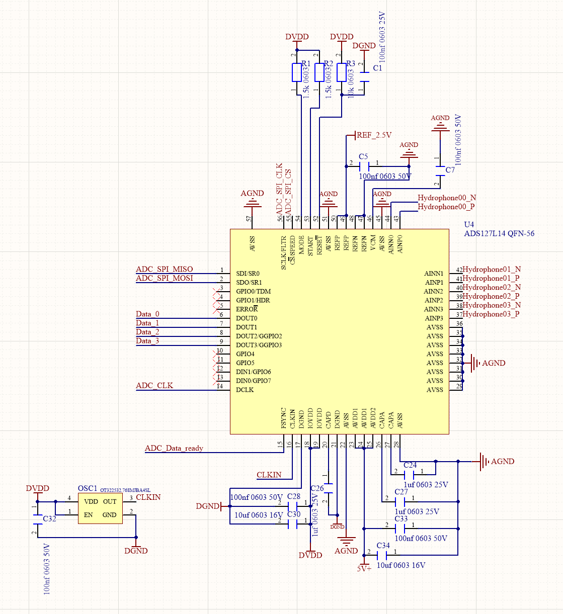
1 in the control register CONTROL_REG_ADDR 0x07 to trigger ADC conversion. However, no valid waveforms are detected on DCLK and DOUT0~DOUT3.
#ifndef __ADS127L14_H__
#define __ADS127L14_H__
#include "stm32h7xx_hal.h"
/*************************基本读写命令宏定义***************************/
#define WR_COMMAND 0x80 //写命令
#define RD_COMMAND 0x00 //读取命令
/*************************寄存器宏定义*********************************/
#define DEV_ID_REG_ADDR 0x00 //芯片ID寄存器地址
#define ADS127L14 0x04 //设备为L14
#define ADS127L18 0x06 //设备位L18
#define STATUS_REG_ADDR 0x02 //状态标志位寄存器地址
#define ALV_FLAG (0x01 << 6) //检测到模拟电源低电压,写一复位
#define POR_FLAG (0x01 << 5) //上电低压复位,写一复位
#define SPI_ERR (0x01 << 4) //SPI_CRC错误,写一复位
#define REG_ERR (0x01 << 3) //寄存器映射 CRC 错误,写一复位
#define ADC_ERR (0x01 << 2) //ADC内部错误,应复位错误才行,复位器件 注意!!!!!!!!!!!!!!!
#define ADDR_ERR (0x01 << 1) //SPI 寄存器地址错误,写一复位
#define SCLK_ERR (0x01 << 0) //SPI SCLK 计数错误,通过写入 1b 可以清除错误。设置 SCLK_CNT_EN = 1b 即可启用 SCLK 计数错误检查。
/*
时钟频率验证寄存器, 时钟计数值寄存器。此寄存器是 ADC 时钟的计数器。此计数器以 fCLK/32 再除以
CLK_DIV[2:0] 设置值的速率递增。应以已知的时间间隔读取寄存器以验证 ADC 时钟频率。时钟计数由 CLK_CNT_EN
寄存器位启用。启用后,计数器值复位为 00h。禁用后,计数值为 00h。*/
#define CLK_CNT_REG_ADDR 0x03
#define CONTROL_REG_ADDR 0x07 //控制寄存器地址
#define RESET_CMD (0x16 << 2) //软件复位
#define START (0x01 << 1) //启动转换,或同步。自动清零
#define STOP (0x01 << 0) //停止转换,自动清零
#define CONTROL_CONFIG 0x00 // 无操作,不复位、不启动、不停止
#define CONTROL_RESET RESET_CMD //复位使用
#define GEN_CFG1_REG_ADDR 0x08 //配置寄存器地址
/*转换启动延迟时间选择。
选择将 START 置为高电平(或设置 START 位)后的转换启动延迟时
间(以 fMOD 周期数表示)。*/
#define START_DELAY_0 (0x000 << 3) //0延时
#define START_DELAY_4 (0x001 << 3) //4延时
#define START_DELAY_8 (0x002 << 3) //8延时
#define START_DELAY_16 (0x003 << 3) //16延时
#define START_DELAY_32 (0x004 << 3) //32延时
#define START_DELAY_128 (0x005 << 3) //128延时
#define START_DELAY_512 (0x006 << 3) //512延时
#define START_DELAY_1024 (0x007 << 3) //1024延时
#define VCM_EN (0x01 << 2) //启用VCM脚供模电压输出,高精度采集,使用外部基准源,可以关闭
#define VCM_DIS (0x00 << 2) //禁用VCM脚供模电压输出,高精度采集,使用外部基准源,可以关闭
#define REFP_BUF_EN (0x01 << 1) //基准电源正缓冲器使能 ,高精度采集要启用
#define REFP_BUF_DIS (0x00 << 1) //基准电源正缓冲器禁用 ,高精度采集要启用
/* 基准电压范围选择 BIT0 */
#define REF_RNG_LOW (0x00 << 0) // 低基准范围 0.5~2.75V
#define REF_RNG_HIGH (0x01 << 0) // 高基准范围 1.0~4.096V(你用这个)
#define GEN_CFG1_CONFIG ( START_DELAY_4 \
| VCM_DIS \
| REFP_BUF_EN \
| REF_RNG_LOW ) //System Usage Configuration
#define GEN_CFG2_REG_ADDR 0x09 //配置寄存器地址
#define AVG_MODE (0x00 << 6) //[1:0] 通道平均模式默认关闭
#define START_MODE_STAR_STOP (0x00 << 3) //[1:0] 0为启动/停止控制模式
#define START_MODE_SYNC (0x02 << 3) //[1:0] 2为同步控制模式
#define SPEED_MODE_L (0x00 << 1) //[1:0] 2速度选择模式低速 3.2m
#define SPEED_MODE_M (0x01 << 1) //[1:0] 2速度选择模式中速 12.8m
#define SPEED_MODE_H (0x02 << 1) //[1:0] 2速度选择模式高速 25.6m
#define SPEED_MODE_VH (0x03 << 1) //[1:0] 2速度选择模式超高速 32.768m
#define STBY_MODE_WORK (0x00 << 0) //待机模式选择 0:空闲模式,器件完全上电,1:待机模式器件模拟部分断断
#define STBY_MODE_IDLE (0x01 << 0) //待机模式选择 0:空闲模式,器件完全上电,1:待机模式器件模拟部分断断
#define GEN_CFG2_CONFIG (START_MODE_STAR_STOP | SPEED_MODE_H | STBY_MODE_WORK) //System Usage Configuration
#define GEN_CFG3_REG_ADDR 0x0A //配置寄存器地址
#define OUT_DRV_HALF (0x01 << 7) //数字输出驱动选择,0:全功率驱动器强度 1:半功率驱动器强度 默认01
#define DATA_16BIT (0x01 << 6) //数据分辨率选择。0:24bit 1:16bit 默认00
#define CLK_CNT_EN (0x01 << 5) //时钟计数器使能。0:禁用 1:启用 默认00
#define SPI_STAT_EN (0x01 << 4) //SPI 状态字节输出使能。 0:禁用 1:使能 默认00
#define SPI_ADDR_EN (0x01 << 3) //SPI 寄存器地址验证使能。0:禁用 1:使能 默认00
#define SCLK_CNT_EN (0x01 << 2) //SPI SCLK 计数验证使能 0:禁用 1:使能 默认00
#define SPI_CRC_EN (0x01 << 1) //SPI CRC 使能。 0:禁用 1:使能 默认00
#define REG_CRC_EN (0x01 << 0) //用寄存器映射 CRC 错误验证 0:禁用 1:使能 默认00
// 禁用宏定义(DISABLE)
#define OUT_DRV_FULL (0x00 << 7) //输出驱动:全功率
#define DATA_24BIT (0x00 << 6) //数据分辨率:24bit
#define CLK_CNT_DISABLE (0x00 << 5) //时钟计数器:禁用
#define SPI_STAT_DISABLE (0x00 << 4) //SPI状态字节:禁用
#define SPI_ADDR_DISABLE (0x00 << 3) //SPI地址验证:禁用
#define SCLK_CNT_DISABLE (0x00 << 2) //SPI SCLK计数:禁用
#define SPI_CRC_DISABLE (0x00 << 1) //SPI CRC:禁用
#define REG_CRC_DISABLE (0x00 << 0) //寄存器CRC:禁用
#define GEN_CFG3_CONFIG (OUT_DRV_HALF | DATA_24BIT | \
CLK_CNT_DISABLE | SPI_STAT_DISABLE | \
SPI_ADDR_DISABLE | SCLK_CNT_DISABLE | \
SPI_CRC_DISABLE | REG_CRC_DISABLE) //System Usage Configuration
#define DP_CFG1_REG_ADDR 0x0B //配置寄存器地址 复位 = 0x20
#define DP_CRC_EN (0x01 << 7) //数据端口 CRC 字节使能。0:禁用 1:使能 默认00
#define DP_STAT_EN (0x01 << 6) //数据端口状态字节使能。。0:禁用 1:使能 默认00
#define DP_TDM_CH1 (0x01 << 4) //数据端口时分多路复用 (TDM) 配置。1个数据通道 默认02
#define DP_TDM_CH2 (0x02 << 4) //数据端口时分多路复用 (TDM) 配置。2个数据通道
#define DP_TDM_CH4 (0x03 << 4) //数据端口时分多路复用 (TDM) 配置。4个数据通道
#define DP_DAISY (0x01 << 1) //数据端口重复数据模式。。0b = TDM 菊花链模式模式 1b = 重复数据模式 默认00
// ==================== 禁用宏 ====================
#define DP_CRC_DISABLE (0x00 << 7) // CRC 关闭
#define DP_STAT_DISABLE (0x00 << 6) // 状态字节 关闭
#define DP_DAISY_NORMAL (0x00 << 1) // 菊花链
#define DP_CFG1_CONFIG ( DP_CRC_DISABLE \
| DP_STAT_DISABLE \
| DP_TDM_CH4 \
| DP_DAISY ) //System Usage Configuration
#define DP_CFG2_REG_ADDR 0x0C //配置寄存器地址 复位 = 0x00
#define DCLK_DIV1 (0x00 << 5) //数据端口 DCLK 分频器 1分频 默认1
#define DCLK_DIV2 (0x01 << 5) //数据端口 DCLK 分频器 2分频
#define DCLK_DIV4 (0x02 << 5) //数据端口 DCLK 分频器 4分频
#define DCLK_DIV8 (0x03 << 5) //数据端口 DCLK 分频器 8分频
#define DOUT_DLY_ADVANCE0 (0x00 << 0) //时序不提前也不延迟
#define DOUT_DLY_ADVANCE1 (0x01 << 0) //时序提前0.3ns 默认提前0.9ns
#define DOUT_DLY_ADVANCE2 (0x02 << 0) //时序提前0.6ns
#define DOUT_DLY_ADVANCE3 (0x03 << 0) //时序提前0.9ns
#define DOUT_DLY_ADVANCE4 (0x04 << 0) //时序提前1.2ns
#define DOUT_DLY_DELAY1 ((0x01 << 0)|(0x01 << 4)) //时序延后0.3ns
#define DOUT_DLY_DELAY2 ((0x02 << 0)|(0x01 << 4)) //时序延后0.6ns
#define DOUT_DLY_DELAY3 ((0x03 << 0)|(0x01 << 4)) //时序延后0.9ns
#define DOUT_DLY_DELAY4 ((0x04 << 0)|(0x01 << 4)) //时序延后1.2ns
#define DP_CFG2_CONFIG ( DCLK_DIV2 | DOUT_DLY_ADVANCE3 ) //System Usage Configuration
#define CLK_CFG_REG_ADDR 0x0D //ADC时钟配置寄存器地址 复位 = 0x00
#define CLK_SEL (0x00 << 3) //00:内部振荡器
#define CLK_SEL_EXTERNAL (0x01 << 3) //01:外部振荡器
#define CLK_DIV1 (0x00 << 0) //1振荡器1分频
#define CLK_DIV2 (0x01 << 0) //1振荡器2分频
#define CLK_DIV3 (0x02 << 0) //1振荡器3分频
#define CLK_DIV4 (0x03 << 0) //1振荡器4分频
#define CLK_DIV8 (0x04 << 0) //1振荡器8分频
#define CLK_CFG_CONFIG ( CLK_SEL_EXTERNAL | CLK_DIV1 ) //System Usage Configuration 外部振荡器,不分频
//#define CLK_CFG_CONFIG ( CLK_SEL | CLK_DIV1 ) //最佳配置 外部振荡器,不分频
/* ADS127L14 通道 CFG1 寄存器地址 */
#define ADS127L14_CH0_CFG1 0x11 // 通道0 配置1
#define ADS127L14_CH1_CFG1 0x19 // 通道1 配置1
#define ADS127L14_CH2_CFG1 0x21 // 通道2 配置1
#define ADS127L14_CH3_CFG1 0x29 // 通道3 配置1
// CHn_MUX[6:4] 通道多路选择 (位 6,5,4)
#define CH_MUX_NORMAL (0x00 << 4) // 000 正常极性(默认)
#define CH_MUX_REVERSE (0x01 << 4) // 001 反向极性
#define CH_MUX_OFFSET_TEST (0x02 << 4) // 010 偏移噪声测试
#define CH_MUX_CMRR_AINP (0x03 << 4) // 011 CMRR测试 AINP
#define CH_MUX_CMRR_AINN (0x04 << 4) // 100 CMRR测试 AINN
#define CH_MUX_NEG_FS (0x05 << 4) // 101 -FS测试
#define CH_MUX_POS_FS (0x06 << 4) // 110 +FS测试
// CHn_INP_RNG[3] 输入量程 (位 3)
#define INP_RNG_1X (0x00 << 3) // 0 1倍量程(推荐)
#define INP_RNG_2X (0x01 << 3) // 1 2倍量程
// CHn_EX_RNG[2] 扩展量程 (位 2)
#define EX_RNG_DISABLE (0x00 << 2) // 0 关闭(推荐)
#define EX_RNG_ENABLE (0x01 << 2) // 1 开启 +25% 量程
// 输入缓冲器 (位 1 和 位 0)
#define BUFN_DISABLE (0x00 << 1) // 禁止 AINN 缓冲
#define BUFN_ENABLE (0x01 << 1) // 使能 AINN 缓冲
#define BUFP_DISABLE (0x00 << 0) // 禁止 AINP 缓冲
#define BUFP_ENABLE (0x01 << 0) // 使能 AINP 缓冲
/* System Usage Configuration */
#define CH_CFG1_DEFAULT (CH_MUX_NORMAL | INP_RNG_1X | EX_RNG_DISABLE | BUFN_ENABLE | BUFP_ENABLE)
/* ADS127L14 通道 CFG2 寄存器地址 宏定义 */
#define ADS127L14_CH0_CFG2 0x12
#define ADS127L14_CH1_CFG2 0x1A
#define ADS127L14_CH2_CFG2 0x22
#define ADS127L14_CH3_CFG2 0x2A
/* =========================================================================
CHn_CFG2 寄存器位定义 (BIT POSITION)
========================================================================= */
#define CHn_PWDN_BIT 5U // 位5:通道电源控制
#define CHn_FLTR_BIT 0U // 位0~4:滤波器选择
/* =========================================================================
通道电源控制 CHn_PWDN (BIT 5)
========================================================================= */
#define CH_PWR_ACTIVE (0U << CHn_PWDN_BIT) // 0:通道正常工作
#define CH_PWR_POWERDOWN (1U << CHn_PWDN_BIT) // 1:通道断电
/* =========================================================================
滤波器与数据速率选择 CHn_FLTR[4:0] (BIT 0~4)
========================================================================= */
//------------------- 宽带滤波器 Wideband -------------------
#define FLTR_WB_OSR32 (0U << CHn_FLTR_BIT) // 宽带滤波器 OSR=32
#define FLTR_WB_OSR64 (1U << CHn_FLTR_BIT) // 宽带滤波器 OSR=64
#define FLTR_WB_OSR128 (2U << CHn_FLTR_BIT) // 宽带滤波器 OSR=128
#define FLTR_WB_OSR256 (3U << CHn_FLTR_BIT) // 宽带滤波器 OSR=256
#define FLTR_WB_OSR512 (4U << CHn_FLTR_BIT) // 宽带滤波器 OSR=512
#define FLTR_WB_OSR1024 (5U << CHn_FLTR_BIT) // 宽带滤波器 OSR=1024
#define FLTR_WB_OSR2048 (6U << CHn_FLTR_BIT) // 宽带滤波器 OSR=2048
#define FLTR_WB_OSR4096 (7U << CHn_FLTR_BIT) // 宽带滤波器 OSR=4096
//------------------- Sinc4 滤波器 -------------------
#define FLTR_SINC4_OSR12 (8U << CHn_FLTR_BIT) // Sinc4 OSR=12
#define FLTR_SINC4_OSR16 (9U << CHn_FLTR_BIT) // Sinc4 OSR=16
#define FLTR_SINC4_OSR24 (10U << CHn_FLTR_BIT) // Sinc4 OSR=24
#define FLTR_SINC4_OSR32 (11U << CHn_FLTR_BIT) // Sinc4 OSR=32
#define FLTR_SINC4_OSR64 (12U << CHn_FLTR_BIT) // Sinc4 OSR=64
#define FLTR_SINC4_OSR128 (13U << CHn_FLTR_BIT) // Sinc4 OSR=128
#define FLTR_SINC4_OSR256 (14U << CHn_FLTR_BIT) // Sinc4 OSR=256
#define FLTR_SINC4_OSR512 (15U << CHn_FLTR_BIT) // Sinc4 OSR=512
#define FLTR_SINC4_OSR1024 (16U << CHn_FLTR_BIT) // Sinc4 OSR=1024
#define FLTR_SINC4_OSR2048 (17U << CHn_FLTR_BIT) // Sinc4 OSR=2048
#define FLTR_SINC4_OSR4096 (18U << CHn_FLTR_BIT) // Sinc4 OSR=4096
//------------------- Sinc4 + Sinc1 组合滤波器 -------------------
#define FLTR_SINC4_SINC1_2 (19U << CHn_FLTR_BIT) // Sinc4(32)+Sinc1(2)
#define FLTR_SINC4_SINC1_4 (20U << CHn_FLTR_BIT) // Sinc4(32)+Sinc1(4)
#define FLTR_SINC4_SINC1_10 (21U << CHn_FLTR_BIT) // Sinc4(32)+Sinc1(10)
#define FLTR_SINC4_SINC1_20 (22U << CHn_FLTR_BIT) // Sinc4(32)+Sinc1(20)
#define FLTR_SINC4_SINC1_40 (23U << CHn_FLTR_BIT) // Sinc4(32)+Sinc1(40)
#define FLTR_SINC4_SINC1_100 (24U << CHn_FLTR_BIT) // Sinc4(32)+Sinc1(100)
#define FLTR_SINC4_SINC1_200 (25U << CHn_FLTR_BIT) // Sinc4(32)+Sinc1(200)
#define FLTR_SINC4_SINC1_400 (26U << CHn_FLTR_BIT) // Sinc4(32)+Sinc1(400)
#define FLTR_SINC4_SINC1_1000 (27U << CHn_FLTR_BIT) // Sinc4(32)+Sinc1(1000)
//------------------- Sinc3 / Sinc3 + Sinc1 -------------------
#define FLTR_SINC3_OSR26667 (28U << CHn_FLTR_BIT) // Sinc3 OSR=26667
#define FLTR_SINC3_OSR32000 (29U << CHn_FLTR_BIT) // Sinc3 OSR=32000
#define FLTR_SINC3_SINC1_3 (30U << CHn_FLTR_BIT) // Sinc3(32000)+Sinc1(3)
#define FLTR_SINC3_SINC1_5 (31U << CHn_FLTR_BIT) // Sinc3(32000)+Sinc1(5)
/* =========================================================================
System Usage Configuration
========================================================================= */
#define CH_CFG2_DEFAULT (CH_PWR_ACTIVE | FLTR_WB_OSR32)
unsigned char ads127l14_init(void);
extern HAL_StatusTypeDef ads_writeReg(unsigned char wr_command, unsigned char reg_addr, unsigned char reg_data);
#endif
unsigned char ads127l14_init(void)
{
static unsigned char operating_state_machine = 0;
HAL_StatusTypeDef status;
unsigned char error_code = 0; //故障码 0正常
unsigned char rx_data = 0;
while(1)
{
switch(operating_state_machine)
{
case 0: //第一阶段读取芯片型号看是否对
error_code = 1;
status = ads_readReg(RD_COMMAND, DEV_ID_REG_ADDR, &rx_data);
if(status == HAL_OK)
{
if(rx_data == ADS127L14)
{
operating_state_machine = 1;
}
}
HAL_Delay(2);
break;
case 1: //第二阶段软件复位一次
error_code = 2;
status = ads_writeReg(WR_COMMAND, CONTROL_REG_ADDR, CONTROL_RESET); //软件复位一次
if(status == HAL_OK)
{
HAL_Delay(400);
operating_state_machine = 2;
}
break;
case 2: //第三阶段设置时钟
error_code = 3;
status = ads_writeReg_withVerify(WR_COMMAND, RD_COMMAND, CLK_CFG_REG_ADDR, CLK_CFG_CONFIG); //设置时钟
if(status == HAL_OK)
{
operating_state_machine = 3;
}
HAL_Delay(2);
break;
case 3: //配置参数寄存器一
error_code = 4;
status = ads_writeReg_withVerify(WR_COMMAND, RD_COMMAND, GEN_CFG1_REG_ADDR, GEN_CFG1_CONFIG); //设置时钟
if(status == HAL_OK)
{
operating_state_machine = 4;
}
HAL_Delay(2);
break;
case 4: //配置参数寄存器二
error_code = 5;
status = ads_writeReg_withVerify(WR_COMMAND, RD_COMMAND, GEN_CFG2_REG_ADDR, GEN_CFG2_CONFIG); //设置时钟
if(status == HAL_OK)
{
operating_state_machine = 5;
}
HAL_Delay(2);
break;
case 5: //配置参数寄存器三
error_code = 6;
status = ads_writeReg_withVerify(WR_COMMAND, RD_COMMAND, GEN_CFG3_REG_ADDR, GEN_CFG3_CONFIG); //设置时钟
if(status == HAL_OK)
{
operating_state_machine = 8;
}
HAL_Delay(2);
break;
case 6: //数据端口 配置参数一
error_code = 7;
status = ads_writeReg_withVerify(WR_COMMAND, RD_COMMAND, DP_CFG1_REG_ADDR, DP_CFG1_CONFIG); //设置时钟
if(status == HAL_OK)
{
operating_state_machine = 7;
}
HAL_Delay(2);
break;
case 7: //数据端口 配置参数二
error_code = 8;
status = ads_writeReg_withVerify(WR_COMMAND, RD_COMMAND, DP_CFG2_REG_ADDR, DP_CFG2_CONFIG); //设置时钟
if(status == HAL_OK)
{
operating_state_machine = 10;
}
HAL_Delay(2);
break;
case 8: //数据通道配置参数一
error_code = 9;
status = ads_writeReg_withVerify(WR_COMMAND, RD_COMMAND, ADS127L14_CH0_CFG1, CH_CFG1_DEFAULT);
HAL_Delay(2);
if(status == HAL_OK)
{
status = ads_writeReg_withVerify(WR_COMMAND, RD_COMMAND, ADS127L14_CH1_CFG1, CH_CFG1_DEFAULT);
HAL_Delay(2);
if(status == HAL_OK)
{
status = ads_writeReg_withVerify(WR_COMMAND, RD_COMMAND, ADS127L14_CH2_CFG1, CH_CFG1_DEFAULT);
HAL_Delay(2);
if(status == HAL_OK)
{
status = ads_writeReg_withVerify(WR_COMMAND, RD_COMMAND, ADS127L14_CH3_CFG1, CH_CFG1_DEFAULT);
HAL_Delay(2);
if(status == HAL_OK)
{
operating_state_machine = 9;
}
}
}
}
HAL_Delay(2);
break;
case 9: //数据通道配置参数二
error_code = 10;
status = ads_writeReg_withVerify(WR_COMMAND, RD_COMMAND, ADS127L14_CH0_CFG2, CH_CFG2_DEFAULT);
HAL_Delay(2);
if(status == HAL_OK)
{
status = ads_writeReg_withVerify(WR_COMMAND, RD_COMMAND, ADS127L14_CH1_CFG2, CH_CFG2_DEFAULT);
HAL_Delay(2);
if(status == HAL_OK)
{
status = ads_writeReg_withVerify(WR_COMMAND, RD_COMMAND, ADS127L14_CH2_CFG2, CH_CFG2_DEFAULT);
HAL_Delay(2);
if(status == HAL_OK)
{
status = ads_writeReg_withVerify(WR_COMMAND, RD_COMMAND, ADS127L14_CH3_CFG2, CH_CFG2_DEFAULT);
HAL_Delay(2);
if(status == HAL_OK)
{
operating_state_machine = 6;
}
}
}
}
HAL_Delay(2);
break;
case 10: //同步下输出
status = ads_writeReg(WR_COMMAND, CONTROL_REG_ADDR, START); //同步下输出
status = ads_writeReg_withVerify(WR_COMMAND, RD_COMMAND, CONTROL_REG_ADDR, START);
if(status == HAL_OK)
{
HAL_Delay(2);
error_code = 0; //正常
return error_code; //返回错误码
}
break;
}
}
// return error_code; //返回错误码
}
Regards,
Danilo